12 Data Center Features
(Aplicável somente ao modelo S3054G-B)
VxLAN
Visão geral
Plano de fundo
Para obter alta confiabilidade e implantação redundante, a maioria das redes corporativas e seus data centers cruzam vários locais físicos em diferentes locais físicos e implantam serviços semelhantes nesses locais. Para integrar os recursos do data center e reduzir o custo de gerenciamento, os recursos do data center geralmente são virtualizados. A tecnologia de virtualização do data center inclui principalmente virtualização de rede, virtualização de armazenamento e virtualização de servidor. Entre eles, a virtualização de servidores consiste em usar um software especial de virtualização para virtualizar várias máquinas virtuais em um servidor físico. Cada máquina virtual é executada de forma independente e possui seu próprio sistema operacional, programa aplicativo e ambiente de hardware virtual. Para realizar a alocação e o gerenciamento dinâmicos de recursos entre sites, as máquinas virtuais devem ser capazes de migrar livremente entre os data centers. Como o processo de migração das máquinas virtuais é transparente para os usuários, o endereço IP não pode ser alterado. Portanto, é necessário que as redes antes e depois da migração das máquinas virtuais estejam na mesma rede L2. Portanto, é necessário realizar a interligação de redes L2 entre sites distribuídos em diferentes locais.
VxLAN é um tipo de tecnologia "MAC in IP", que é usada para realizar a grande interconexão L2 baseada na rede IP core. O VxLAN mantém apenas o endereço MAC e as informações de encaminhamento nos dispositivos de borda do site, sem alterar a rede interna e a estrutura de rede principal do site.
uso de VxLAN como a grande tecnologia de interconexão de rede L2 tem as seguintes vantagens:
- A VxLAN encapsula os pacotes enviados pela máquina virtual em UDP e usa o endereço IP/MAC da rede física como cabeçalho externo para encapsular, que mostra apenas os parâmetros encapsulados. Portanto, o requisito da grande rede L2 para a especificação do endereço MAC é bastante reduzido. Além dos dispositivos de borda de rede vxlan , os outros dispositivos da rede não precisam identificar o endereço MAC da máquina virtual, o que reduz a pressão de aprendizado do endereço MAC e melhora o desempenho do dispositivo.
- O VxLAN introduz um ID de usuário semelhante ao ID de VLAN, que é chamado de identificador de rede VxLAN VNI. É composto por 24 bits e suporta até 16777215 segmentos VxLAN, para atender a um grande número de IDs de usuários.
- Ao usar MAC no encapsulamento UDP para estender a rede L2, a rede física e a rede virtual são desacopladas. Os locatários podem planejar sua própria rede virtual sem considerar as limitações do endereço IP da rede física e do domínio de transmissão, o que reduz bastante a dificuldade de gerenciamento da rede.
Conceitos básicos
Nó de Borda Virtual da Rede
NVE (borda de virtualização de rede) é uma entidade de rede que realiza a função de virtualização de rede. Depois que o pacote é encapsulado e transformado pela entidade de rede NVE, a rede VxLAN virtual pode ser estabelecida entre o NVE com base na rede básica de três camadas.
Ponto final do túnel VxLAN
VTEP ( VxLAN Tunnel End Point ) é um dispositivo de comutação localizado na borda do site. Ele opera como um dispositivo de camada 2 na rede local e um dispositivo L3 na rede central. Ele fornece principalmente interconexão de duas camadas entre redes de sites. Ele conclui o encapsulamento de pacotes da rede local para a rede central e o desencapsulamento de pacotes da rede central para a rede local.
Interface de rede principal: a interface L3 no dispositivo de borda conectado à rede principal, ou seja, Porta de rede .
Interface interna do site: a interface L2 no dispositivo de borda conectado ao dispositivo interno do site, ou seja, Porta Interna .
VxLAN Sessão
VxLAN é estabelecer o túnel VxLAN por meio de configuração manual ou negociação de protocolo e associar a instância VxLAN para formar uma instância de encaminhamento efetiva entre VTEP s. Esta instância é chamada de sessão VxLAN . Os dados só podem ser encaminhados se a sessão vxlan for válida.
EVPN
EVPN (Ethernet Virtual Private Network) é uma tecnologia L2 VPN. A tecnologia EVPN usa o MP-BGP estendido para espalhar as informações do host na rede do usuário entre diferentes sites e usa o plano de controle para substituir o plano de dados para concluir o aprendizado do endereço MAC entre sites na rede do usuário.
VXLAN é apenas um protocolo de encapsulamento de dados. Não define o plano de controle. A aprendizagem de endereços MAC entre sites é completada pela inundação de tráfego do plano de dados tradicional. A maior desvantagem desse método é que há muito tráfego de inundação na rede de rolamentos do data center. A fim resolver este problema, VXLAN introduz EVPN como o plano de controle. Ao trocar rotas BGP EVPN entre VTEPs, realiza a descoberta automática de VTEP e a notificação mútua de informações do host, de modo a evitar inundações de dados desnecessárias.
Especificações do protocolo
- RFC7348: Virtual eXtensible Local Area Network ( VxLAN ): Um Framework para sobreposição de redes de camada 2 virtualizadas em redes de camada 3.
- RFC 7432 : VPN Ethernet baseada em BGP MPLS
- RFC 8365 -- Uma solução de sobreposição de virtualização de rede usando Ethernet VPN (EVPN)
- draft-ietf-bess-evpn-inter-subnet-forwarding-05
- draft-ietf-bess-evpn-prefix-advertisement-11
- draft-malhotra-bess-evpn-irb-extended-mobility-03
função VxLAN
Tabela 2 -1 Lista de configuração da função VxLAN
| Tarefas de configuração | |
| Configurar funções básicas de VxLAN | Configurar instância VxLAN
Configurar informações de descrição da instância VxLAN Configurar a interface VxLAN L3 Configurar aprendizado entre sites Configurar NVE |
| Configurar o VxLAN estático | Configure a lista de cópias do cabeçalho estático VxLAN |
| Configurar EVPN VxLAN | Configure o NVE para habilitar o EVPN
Configure os atributos EVPN da instância VxLAN Configure os atributos EVPN da instância VRF (opcional) Configure o BGP para habilitar o EVPN Configure a política de vizinho BGP (opcional) Configurar o mapa de rotas VxLAN (opcional) |
Configurar VxLAN Instância
Condição de configuração
Nenhum
Configurar VxLAN Instância
Cada instância de VxLAN é uma área de trabalho independente. Por meio do isolamento VNID , diferentes instâncias de VxLAN não podem se comunicar entre si. A mesma instância de VxLAN pode se comunicar entre si. O dispositivo oferece suporte à configuração de até 4.096 instâncias de VxLAN .
Tabela 2 -2 Configurar o VxLAN instância
| Etapa | Comando | Descrição |
| Modo de configuração global | configure terminal | - |
| configuração VxLAN | vxlan vxlan-id | Obrigatório Por padrão, não crie nenhuma VxLAN . |
| Configurar VxLAN VNID | vxlan vnid vnid | Por padrão, ele não está configurado. |
O VNID da instância VxLAN deve ser configurado em prioridade . Caso contrário , outras configurações de serviço não terão efeito.
Configurar informações de descrição da instância VxLAN
Para ser conveniente para memória e gerenciamento, as informações de descrição do VxLAN podem ser configuradas de acordo com o tipo de serviço, função e conexão do VxLAN .
Tabela 2 -3 Configure as informações de descrição de VxLAN
| Etapa | Comando | Descrição |
| Entre no modo de configuração global | configure terminal | - |
| Entre no modo de configuração VxLAN | vxlan vxlan-id | Obrigatório Após entrar no modo de configuração VxLAN , o VxLAN informações de descrição podem ser configuradas. |
| Configurar VxLAN informações de descrição | description description-name | Opcional Por padrão, VxLAN não possui as informações de descrição. |
Acesso ao serviço de instância VxLAN
O VxLAN não contém nenhum ponto de acesso de serviço quando foi criado inicialmente. As máquinas virtuais são conectadas à rede VxLAN usando diferentes métodos de acesso, de modo a realizar o encaminhamento de rede VxLAN para serviços de máquina virtual. O modo de acesso é o seguinte:
Tabela 2 -4 Configurar o modo de ponto de serviço
| Modo | Descrição |
| vlan | Este tipo de interface recebe apenas os pacotes com tag VLAN e a tag VLAN externa que corresponde à tag VLAN especificada; Quando esse tipo de interface encapsula o pacote original com VXLAN, a tag VLAN mais externa será removida; Ao desencapsular o pacote VXLAN , a tag VLAN especificada será adicionada antes do encaminhamento. Neste modo, as portas físicas precisam ser adicionadas à VLAN correspondente e a VLAN global precisa ser criada Este modo suporta o encaminhamento L2 e o encaminhamento L3. |
| qinq | Este tipo de interface recebe apenas os pacotes com duas camadas especificadas de tag VLAN; Quando esse tipo de interface encapsula o pacote original com VXLAN, as duas camadas mais externas de tags VLAN serão removidas; Ao descapsular o pacote VXLAN, as duas camadas especificadas de tags VLAN serão adicionadas antes do encaminhamento. Neste modo, a porta física deve ser adicionada à VLAN externa correspondente e a VLAN global precisa ser criada Este modo suporta o encaminhamento L2 e o encaminhamento L3. |
| desmarcar | tipo de interface só recebe os pacotes sem Tag VLAN . O modo suporta encaminhamento L2 e encaminhamento L3 ao mesmo tempo. |
| predefinição | A interface tem permissão para receber todos os pacotes, independentemente de haver tag VLAN no pacote. Esse tipo de interface não realizará nenhum processamento de tag VLAN para o pacote original, incluindo adição, substituição ou remoção, seja o pacote VLAN encapsulado ou desencapsulado. Este modo suporta apenas o encaminhamento L2 e não suporta o encaminhamento entre VLANs. |
A instância VxLAN não contém nenhum ponto de acesso de serviço quando é criada inicialmente. Você precisa configurá-lo manualmente da seguinte maneira.
Tabela 2 -5 Configurar o ponto de serviço
| Etapa | Comando | Descrição |
| Entre no modo de configuração global | configure terminal | - |
| Configurar o modo de porta | interface tengigabitethernet 0/1 | Obrigatório Após entrar no modo de porta, você pode configurar a porta a ser adicionada à instância VxLAN e oferecer suporte à porta de agregação. |
| Configurar o modo de acesso da instância VxLAN | vxlan vxlan-id encapsulation { vlan vlan-id | qinq svlan svlan-id cvlan cvlan-id | untag | default } | Obrigatório Por padrão, nenhuma porta é adicionada ao VxLAN . a porta for adicionada à VxLAN , a função VxLAN poderá entrar em vigor na porta. |
Quando o modo de acesso é untag e defaul , várias instâncias vxlan não podem ser adicionadas à mesma porta ao mesmo tempo. Quando o modo de acesso é o modo VLAN, a porta de acesso vxlan precisa ser configurada como acesso de tag.
Configurar a interface VxLAN L3
Na função L3 VxLAN , você deve configurar a interface VxLAN L3 e especificar o IP.
Tabela 2 -6 Configurar o VxLAN interface
| Etapa | Comando | Descrição |
| Entre no modo de configuração global | configure terminal | - |
| Configurar o VxLAN interface | interface vxlan vxlan-id | M andatpry padrão, não configure a interface VxLAN . Ao habilitar a função L3 VxLAN , ela deve ser configurada. |
| Configurar a interface VxLAN para associar com VRF | ip vrf forwarding vrf-name | opcional _ Por padrão, a interface VxLAN não está associada ao VRF. |
| Configurar o endereço IP da interface VxLAN | ip address X.X.X.X | Mandatório _ Por padrão, a interface VxLAN não está configurada com o endereço IP. Ao habilitar a função L3 VxLAN , ela deve ser configurada. |
Habilite o Aprendizado de Rota
Depois que o VxLAN habilita a função de aprendizado entre sites, o pacote de solicitação ARP, o pacote de resposta ARP e o pacote ARP livre recebido na porta interna gerarão a rota EVPN local e notificarão os vizinhos através do protocolo BGP EVPN para realizar o aprendizado de rota entre os VTEPs .
Tabela 2 -7 Habilite o aprendizado de rota
| Etapa | Comando | Descrição |
| Entre no modo de configuração global | configure terminal | - |
| Entre no modo de configuração VxLAN | vxlan vxlan-id | Obrigatório |
| Habilite o aprendizado de rota | vxlan local-mac advertise vxlan local-ip advertise | Obrigatório Por padrão, está habilitado. |
Configurar NVE
NVE (borda de virtualização de rede) é uma entidade de rede que realiza a função de virtualização de rede. Após o pacote ser encapsulado e transformado pela entidade de rede NVE, a rede VxLAN virtual pode ser estabelecida entre os NVEs com base na rede básica L3.
Tabela 2 -8 Configurar nve
| Etapa | Comando | Descrição |
| Entre no modo de configuração global | configure terminal | - |
| Crie uma interface nve | interface nve nve-number | Obrigatório Por padrão, não crie a interface NVE no dispositivo. |
| Configurar o endereço IP de origem | source ip-address | Obrigatório VTEP não é configurado na interface NVE. |
Configurar Static VxLAN Túnel
Condição de configuração
Nenhum
Configurar a lista de cópia de cabeçalho estático de VxLAN Instância
O cabeçalho refere-se ao nó de ingresso do túnel VxLAN , e a lista de cópias refere-se a que quando o nó de entrada do túnel VxLAN recebe o pacote BUM ( Broadcast & Unknown-unicast & Multicast ), ele copiará o pacote e o enviará para todos os VTEP s em a lista. A lista de cópias de cabeçalho é a lista de endereços IP do VTEP remoto usado para guiar o nó de ingresso do túnel VxLAN para copiar e enviar o pacote BUM.
A lista de cópias de cabeçalho, também conhecida como túnel BUM VxLAN , copia o pacote BUM recebido de acordo com a lista VTEP e o envia para todos os VTEPs pertencentes ao mesmo VNI através da interface NVE de origem da lista de cópias de cabeçalho.
Tabela 2 -9 Configurar a lista de cópias do cabeçalho estático VxLAN
| Etapa | Comando | Descrição |
| Modo de configuração global | configure terminal | - |
| Modo de configuração da interface NVE | interface nve nve-number | Obrigatório |
| Configure a lista de cópias do cabeçalho estático VxLAN especificado | vxlan vxlan-id ingress-replication peer ip-address | Obrigatório Por padrão, não configure a lista de cópias do cabeçalho estático. |
Mesmo que o VTEP de origem corresponda apenas a um VTEP remoto , é necessário executar o comando para especificar o endereço VTEP correspondente e configurar a lista de cópias de cabeçalho.
Configurar EVPN VxLAN Túnel
Condição de configuração
Antes de configurar o modo BGP EVPN para implantar o serviço VxLAN , primeiro conclua as seguintes tarefas:
- Configure o protocolo da camada de link, garantindo a comunicação normal da camada de link
- Configure o endereço da camada de rede da interface, tornando o nó de rede vizinho acessível na camada de rede
Configurar o NVE para habilitar o protocolo EVPN
Após o NVE ativar o EVPN, negocie e configure automaticamente o túnel VxLAN entre VTEPs por meio do protocolo BGP EVPN.
Tabela 2 -10 Configurar o túnel VxLAN dinâmico
| Etapa | Comando | Descrição |
| Modo de configuração global | configure terminal | - |
| Modo de configuração da interface NVE | interface nve nve-number | Obrigatório |
| Configurar a instância VxLAN especificada para associar NVE | vxlan vxlan-id | Obrigatório Por padrão, não associe . |
| Especifique a instância VxLAN para usar EVPN para configurar a lista de cópias de cabeçalho | vxlan vxlan-id ingress-replication protocol bgp | Opcional Por padrão, não especifique. |
Configure os atributos EVPN da instância VxLAN
RD é usado para identificar rotas EVPN geradas por diferentes VxLANs , de modo a obter o isolamento entre diferentes VxLANs ; route-target é usado para controlar a importação e exportação de rotas EVPN . Quando o VTEP inicia rotas EVPN , ele carrega o atributo Export RT. Quando o VTEP decide para qual VxLAN a rota EVPN é importada, o atributo Export RT carregado pela rota é usado para corresponder ao Import RT do VxLAN local .
Tabela 2 -11 Configurar os atributos VxLAN EVPN
| Etapa | Comando | Descrição |
| Modo de configuração global | configure terminal | - |
| Modo de configuração da instância VxLAN | vxlan vxlan-id | Obrigatório No modo de configuração VxLAN , você pode entrar no modo de configuração EVPN. |
| configuração VxLAN EVPN | address-family evpn | Obrigatório Após entrar no modo VxLAN EVPN , você pode configurar os atributos VxLAN EVPN . |
| Configurar VxLAN rd | rd route-distinguisher | Obrigatório Por padrão, não configure VxLAN RD . |
| Configurar destino de rota VxLAN | route-target [both|export|import] { ASN:nn|IP-address:nn} | Obrigatório padrão, não configure os atributos Exportar, Importar RT de VxLAN . |
Configurar os atributos EVPN da instância VRF ( opcional)
Somente quando o gateway distribuído é implantado, o atributo EVPN da instância VRF precisa ser configurado. Essa configuração é ignorada na implantação de gateway centralizado.
Tabela 2 -12 Configurar os atributos EVPN da instância VRF
| Etapa | Comando | Descrição |
| Modo de configuração global | configure terminal | - |
| Entre no modo de configuração VRF | ip vrf vrf-name | Obrigatório |
| Configurar rd | rd route-distinguisher | Mandatório _ Por padrão, não configure rd. |
| Configurar L3VNID | l3vnid vnid-number | Obrigatório Por padrão, não está configurado.L3VNID. |
| no modo de configuração da família de endereços VRF EVPN | address-family evpn | Obrigatório |
| Configure o destino de rota do VRF EVPN | route-target [ both | export | import ] { ASN:nn|IP-address:nn} | Obrigatório Por padrão, não configure o atributo Importar e Exportar . |
| Um ssociate VRF EVPN com a política de rota de saída. | export map route-map-name | Opcional padrão, o VRF EVPN não está associado à política de rota de saída. |
| Um ssociate VRF EVPN com a política de rota de ingresso. | import map route-map-name | Opcional padrão, o VRF EVPN não está associado à política de rota de ingresso. |
Configurar BGP para habilitar EVPN
BGP habilita o recurso EVPN, fazendo com que o BGP aprenda a rota EVPN, crie um túnel VxLAN dinâmico, forme a sessão VxLAN e adicione à tabela de encaminhamento e guie o encaminhamento de pacotes VxLAN .
Tabela 2 -13 Configurar BGP EVP N para habilitar EVPN
| Etapa | Comando | Descrição |
| Modo de configuração global | configure terminal | - |
| Habilite o protocolo BGP e entre no modo de configuração BGP | router bgp autonomous-system | Obrigatório Por padrão, não está habilitado. |
| Configurar o BGP vizinho | neighbor { neighbor-address | peer-group-name } remote-as as-number | Obrigatório Por padrão, não crie nenhum vizinho BGP. |
| Configurar o endereço de origem da sessão TCP do vizinho BGP | neighbor { neighbor-address | peer-group-name } update-source { interface-name | ip-address } | Opcional Por padrão, as sessões TCP selecionam automaticamente o endereço da interface de saída de rota como o endereço de origem. |
| Entre no modo de configuração BGP EVPN | address-family l2vpn evpn | Obrigatório |
| Ativar o recurso EVPN | neighbor { neighbor-address | peer-group-name } activate | Obrigatório Por padrão, não está ativado. |
| Configurar o refletor EVPN | neighbor { neighbor-address | peer-group-name } route-reflector-client | Opcional Por padrão, não habilite o refletor. |
| modo de configuração BGP IPV4 VRF | address-family ipv4 vrf vrf-name | Opcional |
| Configure a rota unicast VRF para redistribuir para EVPN e formar cinco tipos de rotas | advertise-l2vpn-evpn | Opcional Essa configuração é necessária para a implantação do gateway distribuído. |
| Entre no modo de configuração BGP EVPN | address-family l2vpn evpn | Mandatório _ |
| Quando o BGP é configurado para anunciar rotas para vizinhos ou grupos de pares, não altere os valores de atributo as path, Med e next hop da rota. | neighbor attribute-unchanged[ as-path | med | next-hop ] | Opcional Essa configuração só é necessária ao implantar uma rede VXLAN entre data centers de ponta a ponta. |
Configurar a política de vizinho BGP ( opcional)
Ao vincular o mapa de rotas nos vizinhos BGP EVPN , você pode filtrar efetivamente as rotas com o VNI especificado recebido na direção de entrada ou impedir a publicidade de algumas rotas com o VNI especificado aos vizinhos na direção de saída.
Tabela 2 -14 Configurar a política EVPN do vizinho BGP
| Etapa | Comando | Descrição |
| Modo de configuração global | configure terminal | - |
| Habilite o protocolo BGP e entre no modo de configuração BGP | router bgp autonomous-system | Obrigatório Por padrão, não habilite o BGP. |
| Entre no modo de configuração BGP EVPN | address-family l2vpn evpn | Obrigatório |
| Configurar o vizinho para aplicar o mapa de rotas na direção de ingresso | neighbor { neighbor-address | peer-group-name } route-map rtmap-name in | Obrigatório Por padrão, não aplique o mapa de rota na direção de entrada. |
| Configurar o vizinho para aplicar o mapa de rotas na direção de saída | neighbor { neighbor-address | peer-group-name } route-map rtmap-name out | Obrigatório Por padrão, não aplique o mapa de rota na direção de saída. |
Configurar o mapa de rotas VxLAN ( opcional )
Ao configurar a política de VxLAN vizinha , é necessário vincular o mapa de rotas e usar o mapa de rotas para corresponder ao número VxLAN local , ao próximo salto da rota e outros itens correspondentes para controlar as rotas de entrada e saída.
Tabela 2 -15 Configurar o VxLAN mapa de rotas
| Etapa | Comando | Descrição |
| Entre no modo de configuração global | configure terminal | - |
| C rie o mapa de rotas | route-map map-name [ { permit | deny } [ seq-number ] ] | Obrigatório Por padrão, não crie o mapa de rotas. |
| Combine vxlan -id | match vxlan vxlan-id | Opcional padrão, não corresponde ao VxLAN No. |
Monitoramento e manutenção de VxLAN
Tabela 2 -16 VxLAN monitoramento e manutenção
| Comando | Descrição |
| show bgp l2vpn evpn { all | rd route-distinguisher | vxlan-id } { all-type | type { 2 [eth-tag-id:ip-addr-len:ip-address] | 3 [eth-tag-id:mac-addr-len:mac-addr:ip-addr-len:ip-addr]}} | 5 [eth-tag-id:ip-addr-len:ip-addr] | Exiba as informações de rota na família de endereços BGP MVPN |
| show bgp l2vpn evpn conf | Exiba as informações de configuração do EVPN |
| show bgp l2vpn evpn {vxlan vxlan-id | vrf vrf-name} | Exiba as informações EVPN VxLAN /VRF |
| show bgp l2vpn evpn { all | rd route-distinguisher |vxlan-id } neignbors ip-address { advertised-routes | received-routes | routes}{ all-type | type 2 | type 3| type 5 } | Exiba as informações de rota do vizinho especificado sob o cluster de endereços BGP EVPN |
| show bgp l2vpn evpn vxlan-id statistics | Exiba as estatísticas de roteamento do VxLAN especificado no cluster de endereços BGP EVPN |
| show bgp l2vpn evpn summary | Exibir informações de resumo do vizinho do BGP EVPN |
| show vxlan vxlan-id arp-auto-reply | Exiba as informações da tabela de resposta arp da instância VxLAN especificada |
| show vxlan vxlan-id config | Exiba as informações de configuração para uma instância VxLAN especificada |
| show vxlan vxlan-id instance | D isplay as informações de instância do VxLAN especificado |
| show vxlan vxlan-id internal | Exiba o ponto de acesso de serviço da instância VxLAN especificada |
| show vxlan vxlan-id session | Exibe todas as informações de sessão associadas à instância VxLAN especificada |
| show vxlan arp-auto-reply | Exibir informações da tabela de resposta ARP da instância VxLAN |
| show vxlan config | Exiba as informações globais de VxLAN |
| show vxlan instance | Exiba as informações da instância VxLAN |
| show vxlan internal [interface interface-num | interface link-aggregation link-aggregation-id ] | Exiba o ponto de sucesso do serviço VxLA |
| show vxlan tunnel | Exiba as informações do túnel VxLAN |
| show vxlan session | D isplay as informações da sessão VxLAN |
Exemplo de configuração típica de VXLAN
Configurar Static VXLAN para realizar a intercomunicação L2
Requisitos de rede
- Leaf1 e leaf2 servem como VTEP para criar a instância VXLAN .
- Leaf1 e Leaf2 configuram o túnel VXLAN estático por meio da interface de loopback.
- O túnel VXLAN é estabelecido para realizar o interfuncionamento da VM entre o servidor 1 e o servidor2 do mesmo segmento de rede.
Topologia de rede

Figura 2 -1 Rede de configuração da VXLAN estática para realizar a intercomunicação L2
Etapas de configuração
- Passo 1:Configure a VLAN e adicione a porta à VLAN correspondente (omitida).
- Passo 2:Configure o endereço IP da interface.
#Configure Leaf1.
Leaf1(config)#interface loopback 0Leaf1(config-if-loopback0)#ip address 10.0.0.1 255.255.255.255Leaf1(config-if-loopback0)#exitLeaf1(config)#interface vlan 3Leaf1(config-if-vlan3)#ip address 2.0.0.1 255.255.255.0Leaf1(config-if-vlan3)#exit
#Configure Leaf2 .
Leaf2(config)#interface loopback 0Leaf2(config-if-loopback0)#ip address 20.0.0.1 255.255.255.255Leaf2(config-if-loopback0)#exitLeaf2(config)#interface vlan 3Leaf2(config-if-vlan3)#ip address 2.0.0.2 255.255.255.0Leaf2(config-if-vlan3)#exit
- Passo 3:Configurar o OSPF, tornando as rotas de Loopback entre os dispositivos alcançáveis.
#Configure Leaf1 .
Leaf1#configure terminalLeaf1(config)#router ospf 100Leaf1(config-ospf)#network 10.0.0.1 0.0.0.0 area 0Leaf1(config-ospf)#network 2.0.0.0 0.0.0.255 area 0Leaf1(config-ospf)#exit
#Configure Leaf2 .
Leaf2#configure terminalLeaf2(config)#router ospf 100Leaf2(config-ospf)#network 20.0.0.1 0.0.0.0 area 0Leaf2(config-ospf)#network 2.0.0.0 0.0.0.255 area 0Leaf2(config-ospf)#exit
# Visualize a tabela de rotas de Leaf1 .
Leaf1#show ip routeCodes: C - connected, S - static, R - RIP, O - OSPF, OE-OSPF External, M - ManagementD - Redirect, E - IRMP, EX - IRMP external, o - SNSP, B - BGP, i-ISISGateway of last resort is not setC 2.0.0.0/24 is directly connected, 00:05:40, vlan3C 127.0.0.0/8 is directly connected, 1d:21:38:36, lo0C 10.0.0.1/32 is directly connected, 00:06:34, loopback0O 20.0.0.1/32 [110/2] via 2.0.0.2, 00:00:05, vlan3
# Visualize a tabela de rotas do Leaf2 .
Leaf2#show ip routeCodes: C - connected, S - static, R - RIP, O - OSPF, OE-OSPF External, M - ManagementD - Redirect, E - IRMP, EX - IRMP external, o - SNSP, B - BGP, i-ISISGateway of last resort is not setC 2.0.0.0/24 is directly connected, 00:06:43, vlan3C 127.0.0.0/8 is directly connected, 1w3d:03:35:57, lo0O 10.0.0.1/32 [110/2] via 2.0.0.1, 00:02:36, vlan3C 20.0.0.1/32 is directly connected, 00:07:07, loopback0
Pode-se ver que leaf1 e leaf2 aprendem a rota da porta de loop de pares executando o protocolo OSPF, que é preparado para leaf1 e leaf2 estabelecerem vizinhos IBGP através da porta de loopback.
- Passo 4:Configure VXLAN e associe VNID para adicionar portas de leaf1 e leaf2 a VXLAN .
#Configure Leaf1 .
Leaf1(config)# vxlan 100Leaf1(config-vxlan-100)#vxlan vnid 100Leaf1(config-vxlan-100)#exitLeaf1(config)# interface tengigabitethernet 0/1Leaf1(config-if-tengigabitethernet0/1)# vxlan 100 encapsulation vlan 2Leaf1(config-if-tengigabitethernet0/1)#exit
#Configure Leaf2 .
Leaf2(config)# vxlan 100Leaf2(config-vxlan-100)#vxlan vnid 100Leaf2(config-vxlan-100)#exitLeaf2(config)# interface tengigabitethernet 0/1Leaf2(config-if-tengigabitethernet0/1)# vxlan 100 encapsulation vlan 2Leaf2(config-if-tengigabitethernet0/1)#exit
# Visualize as informações VXLAN de Leaf1.
Leaf1#show vxlan 100 configvxlan 100vxlan vnid 100exitLeaf1#show running-config interface te0/1interface tengigabitethernet0/1switchport mode trunkswitchport trunk allowed vlan add 2switchport trunk pvid vlan 1vxlan 100 encapsulation vlan 2exit
# Visualize as informações de VXLAN do Leaf2.
Leaf2#show vxlan 100 configvxlan 100vxlan vnid 100exitLeaf2#show running-config interface te0/1interface tengigabitethernet0/1switchport mode trunkswitchport trunk allowed vlan add 2switchport trunk pvid vlan 1vxlan 100 encapsulation vlan 2exit
- Passo 5:Configurar o túnel VXLAN estático.
#Configure a interface NVE de Leaf1 e os membros de replicação de cabeçalho estático da VXLAN correspondente .
Leaf1(config)#interface nve 1Leaf1(config-if-nve1)#source 10.0.0.1Leaf1(config-if-nve1)#vxlan 100 ingress-replication peer 20.0.0.1Leaf1(config-if-nve1)#exit
#Configure a interface NVE de Leaf2 e os membros de replicação de cabeçalho estático da VXLAN correspondente .
Leaf2(config)#interface nve 1Leaf2(config-if-nve1)#source 20.0.0.1Leaf2(config-if-nve1)#vxlan 100 ingress-replication peer 10.0.0.1Leaf2(config-if-nve1)#exit
# Visualize as informações do túnel e a sessão VXLAN de Leaf1.
Leaf1# show vxlan tunnelNumber of vxlan tunnel: 1---- ---------- ------------------- ------------------- ----------NO. TunnelID Source Destination State---- ---------- ------------------- ------------------- ----------1 32768 10.0.0.1 20.0.0.1 up
Você pode ver que o túnel VXLAN em Leaf1 foi estabelecido com sucesso e está no estado ativo.
Leaf1#show vxlan sessionNumber of vxlan session: 1---- ---------- ---------- ---------- ------------------- ------------------- ----------NO. VXLAN-ID SessionID TunnelID Source Destination State---- ---------- ---------- ---------- ------------------- ------------------- ----------1 100 32768 32768 10.0.0.1 20.0.0.1 up
Você pode ver que a sessão VXLAN com VXLAN -ID 100 em leaf1 liga com sucesso o túnel com a identificação de túnel 32768 e o status está ativo.
# Visualize as informações de VXLAN do Leaf2.
Leaf2# show vxlan tunnelNumber of vxlan tunnel: 1---- ---------- ------------------- ------------------- ----------NO. TunnelID Source Destination State---- ---------- ------------------- ------------------- ----------1 32768 20.0.0.1 10.0.0.1 up
VXLAN no Leaf2 foi configurado com sucesso e o status é UP.
Leaf2#show vxlan sessionNumber of vxlan session: 1---- ---------- ---------- ---------- ------------------- ------------------- ----------NO. VXLAN-ID SessionID TunnelID Source Destination State---- ---------- ---------- ---------- ------------------- ------------------- ----------1 100 32768 32768 20.0.0.1 10.0.0.1 up
Você pode ver que a sessão VXLAN com VXLAN -ID 100 em leaf2 liga com sucesso o túnel com a ID de túnel 32768 e o status está ativo.
- Passo 6:Confira o resultado
# VM1 no Server1 faz ping em VM1 no Server2.
C:\Documents and Settings\ Server 1> ping 1.0.0.2Pinging 1.0.0.2 with 32 bytes of data:Reply from 1.0.0.2: bytes=32 time<1ms TTL=255Reply from 1.0.0.2: bytes=32 time<1ms TTL=255Reply from 1.0.0.2: bytes=32 time<1ms TTL=255Reply from 1.0.0.2: bytes=32 time<1ms TTL=255Ping statistics for 1.0.0.2:Packets: Sent = 4, Received = 4, Lost = 0 (0% loss),Approximate round trip times in milli-seconds:Minimum = 0ms, Maximum = 0ms, Average = 0m
Pode ser visto que Server1 e server2 podem cruzar a rede L3 entre leaf1 e leaf2 para realizar a intercomunicação.
Configurar BGP EVPN VXLAN para realizar a intercomunicação L2
Requisitos de rede
- Leaf1 e leaf2 servem como VTEP para criar a instância VXLAN .
- Leaf1 e Leaf 2 criam o túnel BGP EVPN VXLAN, realizando a intercomunicação do Server1 e Server2 no mesmo segmento.
Topologia de rede

Figura 2 -2 Rede de configuração do BGP EVPN VXLAN para realizar a intercomunicação L2
Etapas de configuração
- Passo 1:Configurar a VLAN e adicionar as portas à VLAN correspondente (omitido).
- Passo 2:Configurar o endereço IP da interface.
#Configure a Folha1 .
Leaf1(config)#interface loopback 0Leaf1(config-if-loopback0)#ip address 10.0.0.1 255.255.255.255Leaf1(config-if-loopback0)#exitLeaf1(config)#interface vlan 3Leaf1(config-if-vlan3)#ip address 2.0.0.1 255.255.255.0Leaf1(config-if-vlan3)#exit
#Configure Leaf2 .
Leaf2(config)#interface loopback 0Leaf2(config-if-loopback0)#ip address 20.0.0.1 255.255.255.255Leaf2(config-if-loopback0)#exitLeaf2(config)#interface vlan 3Leaf2(config-if-vlan3)#ip address 2.0.0.2 255.255.255.0Leaf2(config-if-vlan3)#exit
- Passo 3:Configurar o OSPF, tornando a rota Loopback entre dispositivos alcançável.
#Configure Leaf1 .
Leaf1#configure terminalLeaf1(config)#router ospf 100Leaf1(config-ospf)#network 10.0.0.1 0.0.0.0 area 0Leaf1(config-ospf)#network 2.0.0.0 0.0.0.255 area 0Leaf1(config-ospf)#exit
#Configure Leaf2 .
Leaf2#configure terminalLeaf2(config)#router ospf 100Leaf2(config-ospf)#network 20.0.0.1 0.0.0.0 area 0Leaf2(config-ospf)#network 2.0.0.0 0.0.0.255 area 0Leaf2(config-ospf)#exit
# Visualize a tabela de rotas de Leaf1 .
Leaf1#show ip routeCodes: C - connected, S - static, R - RIP, O - OSPF, OE-OSPF External, M - ManagementD - Redirect, E - IRMP, EX - IRMP external, o - SNSP, B - BGP, i-ISISGateway of last resort is not setC 2.0.0.0/24 is directly connected, 00:05:40, vlan3C 127.0.0.0/8 is directly connected, 1d:21:38:36, lo0C 10.0.0.1/32 is directly connected, 00:06:34, loopback0O 20.0.0.1/32 [110/2] via 2.0.0.2, 00:00:05, vlan3
# Visualize a tabela de rotas do Leaf2 .
Leaf2#show ip routeCodes: C - connected, S - static, R - RIP, O - OSPF, OE-OSPF External, M - ManagementD - Redirect, E - IRMP, EX - IRMP external, o - SNSP, B - BGP, i-ISISGateway of last resort is not setC 2.0.0.0/24 is directly connected, 00:06:43, vlan3C 127.0.0.0/8 is directly connected, 1w3d:03:35:57, lo0O 10.0.0.1/32 [110/2] via 2.0.0.1, 00:02:36, vlan3C 20.0.0.1/32 is directly connected, 00:07:07, loopback0
Podemos ver que leaf1 e leaf2 aprenderam a rota da porta de loopback de peer executando o protocolo OSPF.
- Passo 4:Configure o VXLAN e associe o VNID e configure a família de endereços EVPN para adicionar portas de leaf1 e leaf2 ao VXLAN .
#Configure Leaf1 .
Leaf1(config)# vxlan 100Leaf1(config-vxlan-100)#vxlan vnid 100Leaf1(config-vxlan-100)#address-family evpnLeaf1(config-vxlan-evpn)#rd 100:1Leaf1(config-vxlan-evpn)#route-target both 100:1Leaf1(config-vxlan-evpn)#exitLeaf1(config-vxlan-100)#exitLeaf1(config)# interface tengigabitethernet 0/1Leaf1(config-if-tengigabitethernet0/1)# vxlan 100 encapsulation vlan 2Leaf1(config-if-tengigabitethernet0/1)#exit
#Configure Leaf2 .
Leaf2(config)# vxlan 100Leaf2(config-vxlan-100)#vxlan vnid 100Leaf2(config-vxlan-100)#address-family evpnLeaf2(config-vxlan-evpn)#rd 100:1Leaf2(config-vxlan-evpn)#route-target both 100:1Leaf2(config-vxlan-evpn)#exitLeaf2(config-vxlan-100)#exitLeaf2(config)# interface tengigabitethernet 0/1Leaf2(config-if-tengigabitethernet0/1)# vxlan 100 encapsulation vlan 2Leaf2(config-if-tengigabitethernet0/1)#exit
# Visualize as informações VXLAN de Leaf1.
Leaf1#show vxlan 100 configvxlan 100vxlan vnid 100address-family evpnrd 100:1route-target import 100:1route-target export 100:1exitexitLeaf1#show running-config interface te0/1interface tengigabitethernet0/1switchport mode trunkswitchport trunk allowed vlan add 2switchport trunk pvid vlan 1vxlan 100 encapsulation vlan 2exit
# Visualize as informações de VXLAN do Leaf2.
Leaf2#show vxlan 100 configvxlan 100vxlan vnid 100address-family evpnrd 100:1route-target import 100:1route-target export 100:1exitexitLeaf2#show running-config interface te0/1interface tengigabitethernet0/1switchport mode trunkswitchport trunk allowed vlan add 2switchport trunk pvid vlan 1vxlan 100 encapsulation vlan 2exit
- Passo 5:Configurar BGP.
#Configure Leaf1 .
Configure para estabelecer um peer EBGP conectado diretamente com leaf2 e ative o recurso de notificação na família de endereços EBGP .
Leaf1(config)#router bgp 100Leaf1(config-bgp)#neighbor 2.0.0.2 remote-as 200Leaf1(config-bgp)#address-family l2vpn evpnLeaf1(config-bgp-af)#neighbor 2.0.0.2 activateLeaf1(config-bgp-af)#exit-address-familyLeaf1(config-bgp)#exit
#Configure Leaf2 .
Configure para estabelecer um peer EBGP conectado diretamente com leaf2 e ative o recurso de notificação na família de endereços EVPN .
Leaf2(config)#router bgp 200Leaf2(config-bgp)#neighbor 2.0.0.1 remote-as 100Leaf2(config-bgp)#address-family l2vpn evpnLeaf2(config-bgp-af)#neighbor 2.0.0.1 activateLeaf2(config-bgp-af)#exit-address-familyLeaf2(config-bgp)#exit
# Visualize o vizinho BGP EVPN de Leaf1 .
Leaf1#show bgp l2vpn evpn summaryBGP router identifier 10.0.0.1, local AS number 100BGP table version is 51 BGP AS-PATH entries0 BGP community entriesNeighbor V AS MsgRcvd MsgSent TblVer InQ OutQ Up/Down State/PfxRcd2.0.0.2 4 200 52 50 4 0 0 00:42:18 0Total number of neighbors 1
# Visualize o vizinho BGP EVPN de Leaf2 .
Leaf2#show bgp l2vpn evpn summaryBGP router identifier 20.0.0.1, local AS number 200BGP table version is 51 BGP AS-PATH entries0 BGP community entriesNeighbor V AS MsgRcvd MsgSent TblVer InQ OutQ Up/Down State/PfxRcd2.0.0.1 4 100 52 53 5 0 0 00:43:20 0Total number of neighbors 1
Podemos ver que leaf1 e leaf2 estabeleceram com sucesso vizinhos BGP EVPN
- Passo 6:Configurar a interface NVE .
#Configure a interface NVE de Leaf1 e configure a VXLAN correspondente , e use o protocolo BGP para construir o túnel L2 dinamicamente.
Leaf1(config)#interface nve 1Leaf1(config-if-nve1)#source 10.0.0.1Leaf1(config-if-nve1)#vxlan 100 ingress-replication protocol bgpLeaf1(config-if-nve1)#exit
#Configure a interface NVE do Leaf2 e configure o VXLAN correspondente , e use o protocolo BGP para construir o túnel L2 dinamicamente.
Leaf2(config)#interface nve 1Leaf2(config-if-nve1)#source 20.0.0.1Leaf2(config-if-nve1)#vxlan 100 ingress-replication protocol bgpLeaf2(config-if-nve1)#exit
# Visualize as informações do túnel e a sessão VXLAN de Leaf1.
Leaf1# show vxlan tunnelNumber of vxlan tunnel: 1---- ---------- ------------------- ------------------- ----------NO. TunnelID Source Destination State---- ---------- ------------------- ------------------- ----------1 32768 10.0.0.1 20.0.0.1 upLeaf1#show vxlan sessionNumber of vxlan session: 1---- ---------- ---------- ---------- ------------------- ------------------- ----------NO. VXLAN-ID SessionID TunnelID Source Destination State---- ---------- ---------- ---------- ------------------- ------------------- ----------1 100 32768 32768 10.0.0.1 20.0.0.1 up
# Visualize as informações do túnel e a sessão VXLAN do Leaf2.
Leaf2# show vxlan tunnelNumber of vxlan tunnel: 1---- ---------- ------------------- ------------------- ----------NO. TunnelID Source Destination State---- ---------- ------------------- ------------------- ----------1 32768 20.0.0.1 10.0.0.1 upLeaf2#show vxlan sessionNumber of vxlan session: 1---- ---------- ---------- ---------- ------------------- ------------------- ----------NO. VXLAN-ID SessionID TunnelID Source Destination State---- ---------- ---------- ---------- ------------------- ------------------- ----------1 100 32768 32768 20.0.0.1 10.0.0.1 up
Das informações acima, podemos ver que o túnel está ativo e a sessão multicast dinâmica VXLAN entre Leaf1 e Leaf2 pode ser estabelecida normalmente. Até agora, o tráfego L2 BUM pode ser encaminhado entre Leaf1 e Leaf2.
- Passo 7:V M1 do Server1 e VM1 od Server pingam os diferentes endereços de diferentes segmentos , respectivamente , e visualizam a sessão VXLAN de Leaf1 e Leaf2.
# Visualize a sessão VXLAN de Leaf1.
Leaf1#show vxlan session 20.0.0.1vxlan session 32768state: upsource IP: 10.0.0.1destination IP: 20.0.0.1source mac: 0001.7a00.5278destination mac: 0001.7a21.81e7interface: vlan3switchport: tengigabitethernet0/2vxlan list: 100vxlan unicast list: 100vxlan multicast list: 100
# Visualize a sessão VXLAN do Leaf2.
Leaf2#show vxlan session 10.0.0.1vxlan session 32768state: upsource IP: 20.0.0.1destination IP: 10.0.0.1source mac: 0001.7a21.81e7destination mac: 0001.7a00.5278interface: vlan3switchport: tengigabitethernet0/2vxlan list: 100vxlan unicast list: 100vxlan multicast list: 100
Pode-se ver que as sessões dinâmicas de unicast foram estabelecidas e o tráfego de unicast L2 pode ser encaminhado.
- Passo 8:Confira o resultado
# VM1 do Server1 pinga VM1 do Server2.
C:\Documents and Settings\ Server 1> ping 1.0.0.2Pinging 1.0.0.2 with 32 bytes of data:Reply from 1.0.0.2: bytes=32 time<1ms TTL=255Reply from 1.0.0.2: bytes=32 time<1ms TTL=255Reply from 1.0.0.2: bytes=32 time<1ms TTL=255Reply from 1.0.0.2: bytes=32 time<1ms TTL=255Ping statistics for 1.0.0.2:Packets: Sent = 4, Received = 4, Lost = 0 (0% loss),Approximate round trip times in milli-seconds:Minimum = 0ms, Maximum = 0ms, Average = 0m
Você pode ver que Server1 e Server2 podem cruzar a rede L3 entre Leaf1 e Leaf2 para realizar a intercomunicação.
BGP EVPN suporta IBGP e EBGP. Depois que o BGP habilita o recurso EVPN VXLAN, o vizinho BGP será redefinido automaticamente.
Configurar o gateway VXLAN centralizado estático
Requisitos de rede
- Crie instâncias VXLAN em Leaf1, Spine1 e Leaf2, respectivamente
- Leaf1, Spine1 e Leaf2 estabelecem um túnel VXLAN estático por meio da interface de loopback e atuam como gateway centralizado VXLAN na espinha1 para realizar interfuncionamento entre servidores do mesmo segmento de rede Server1 e Server3 e servidores de diferentes segmentos de rede server2 e Server3.
Topologia de rede
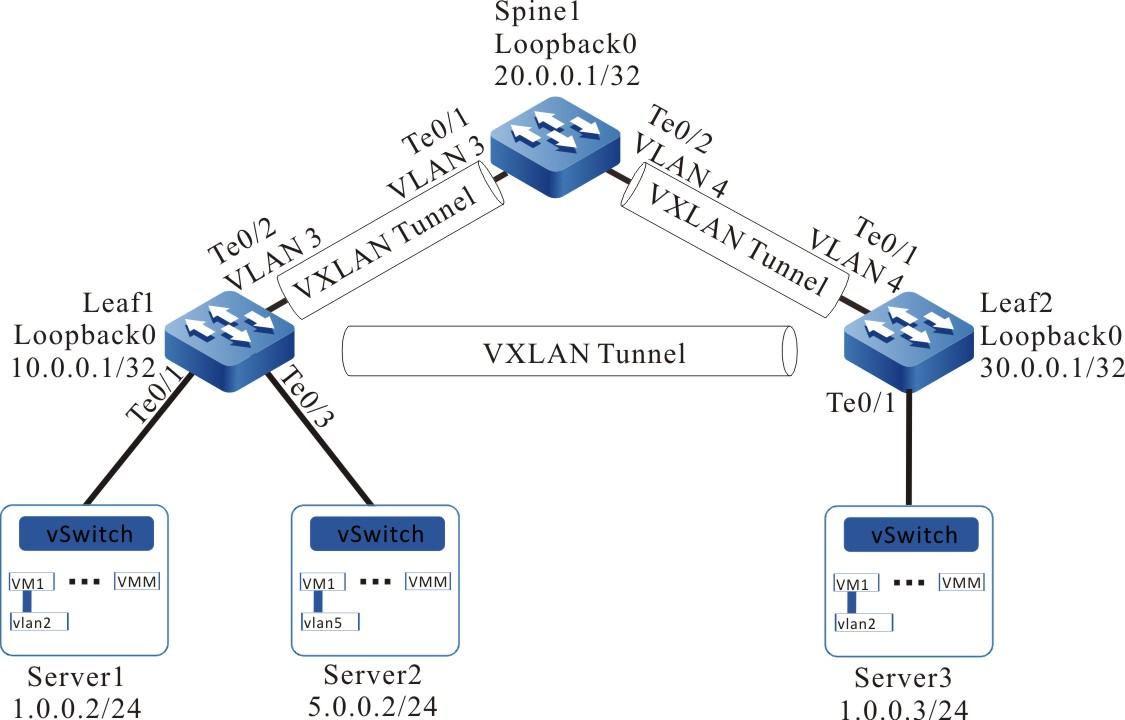
Figura 2 -3 Rede de configuração do gateway VXLAN centralizado estático
Etapas de configuração
- Passo 1:Configure a VLAN e adicione as portas à VLAN correspondente (omitida).
- Passo 2:Configure o endereço IP da interface.
#Configure Leaf1.
Leaf1(config)#interface loopback 0Leaf1(config-if-loopback0)#ip address 10.0.0.1 255.255.255.255Leaf1(config-if-loopback0)#exitLeaf1(config)#interface vlan 3Leaf1(config-if-vlan3)#ip address 2.0.0.1 255.255.255.0Leaf1(config-if-vlan3)#exit
#Configure Spine1.
Spine1(config)#interface loopback 0Spine1(config-if-loopback0)#ip address 20.0.0.1 255.255.255.255Spine1(config-if-loopback0)#exitSpine1(config)#interface vlan 3Spine1(config-if-vlan3)#ip address 2.0.0.2 255.255.255.0Spine1(config-if-vlan3)#exitSpine1(config)#interface vlan 4Spine1(config-if-vlan4)#ip address 3.0.0.1 255.255.255.0Spine1(config-if-vlan4)#exit
#Configure Leaf2.
Leaf2(config)#interface loopback 0Leaf2(config-if-loopback0)#ip address 30.0.0.1 255.255.255.255Leaf2(config-if-loopback0)#exitLeaf2(config)#interface vlan 4Leaf2(config-if-vlan4)#ip address 3.0.0.2 255.255.255.0Leaf2(config-if-vlan4)#exit
- Passo 3:Configure o OSPF, tornando a rota de Loopback entre dispositivos alcançável.
#Configure Leaf1 .
Leaf1#configure terminalLeaf1(config)#router ospf 100Leaf1(config-ospf)#network 10.0.0.1 0.0.0.0 area 0Leaf1(config-ospf)#network 2.0.0.0 0.0.0.255 area 0Leaf1(config-ospf)#exit
#Configure Spine1 .
Spine1#configure terminalSpine1(config)#router ospf 100Spine1(config-ospf)#network 20.0.0.1 0.0.0.0 area 0Spine1(config-ospf)#network 2.0.0.0 0.0.0.255 area 0Spine1(config-ospf)#network 3.0.0.0 0.0.0.255 area 0Spine1(config-ospf)#exit
#Configure Leaf2 .
Leaf2#configure terminalLeaf2(config)#router ospf 100Leaf2(config-ospf)#network 30.0.0.1 0.0.0.0 area 0Leaf2(config-ospf)#network 3.0.0.0 0.0.0.255 area 0Leaf2(config-ospf)#exit
#Visualize a tabela de rotas da Folha 1.
Leaf1#show ip routeCodes: C - connected, S - static, R - RIP, O - OSPF, OE-OSPF External, M - ManagementD - Redirect, E - IRMP, EX - IRMP external, o - SNSP, B - BGP, i-ISISGateway of last resort is not setC 2.0.0.0/24 is directly connected, 00:28:27, vlan3O 3.0.0.0/24 [110/2] via 2.0.0.2, 00:00:05, vlan3C 127.0.0.0/8 is directly connected, 2d:23:06:31, lo0C 10.0.0.1/32 is directly connected, 1d:01:34:29, loopback0O 20.0.0.1/32 [110/2] via 2.0.0.2, 00:00:05, vlan3O 30.0.0.1/32 [110/3] via 2.0.0.2, 00:00:05, vlan3
#Visualize a tabela de rotas do Spine 1.
Spine1#show ip routeCodes: C - connected, S - static, R - RIP, O - OSPF, OE-OSPF External, M - ManagementD - Redirect, E - IRMP, EX - IRMP external, o - SNSP, B - BGP, i-ISISGateway of last resort is not setC 2.0.0.0/24 is directly connected, 07:04:46, vlan3C 3.0.0.0/24 is directly connected, 00:23:50, vlan4C 127.0.0.0/8 is directly connected, 1w4d:05:02:08, lo0O 10.0.0.1/32 [110/2] via 2.0.0.1, 00:00:57, vlan3C 20.0.0.1/32 is directly connected, 1d:01:33:17, loopback0O 30.0.0.1/32 [110/2] via 3.0.0.2, 00:01:33, vlan4
#Visualize a tabela de rotas da Folha 2.
Leaf2#show ip routeCodes: C - connected, S - static, R - RIP, O - OSPF, OE-OSPF External, M - ManagementD - Redirect, E - IRMP, EX - IRMP external, o - SNSP, B - BGP, i-ISISGateway of last resort is not setO 2.0.0.0/24 [110/2] via 3.0.0.1, 00:02:43, vlan4C 3.0.0.0/24 is directly connected, 00:22:14, vlan4C 30.0.0.0/24 is directly connected, 00:23:24, loopback0C 127.0.0.0/8 is directly connected, 4d:00:16:59, lo0O 10.0.0.1/32 [110/3] via 3.0.0.1, 00:02:07, vlan4O 20.0.0.1/32 [110/2] via 3.0.0.1, 00:02:43, vlan4
Podemos ver que Leaf1, Spine1 e Leaf2 aprenderam a rota da porta de loopback de peer executando o protocolo OSPF.
- Passo 4:Configure o VXLAN e associe o VNID para fazer com que as portas de Leaf1 e Spine1 sejam adicionadas ao VXLAN.
#Configure Leaf1.
Leaf1(config)#vxlan 100Leaf1(config-vxlan-100)#vxlan vnid 100Leaf1(config-vxlan-100)#exitLeaf1(config)# interface tengigabitethernet 0/1Leaf1(config-if-tengigabitethernet0/1)# vxlan 100 encapsulation vlan 2Leaf1(config-if-tengigabitethernet0/1)#exitLeaf1(config)#vxlan 200Leaf1(config-vxlan-200)#vxlan vnid 200Leaf1(config-vxlan-200)#exitLeaf1(config)# interface tengigabitethernet 0/3Leaf1(config-if-tengigabitethernet0/3)# vxlan 200 encapsulation vlan 5Leaf1(config-if-tengigabitethernet0/3)#exit
#Configure Spine1 .
Spine1(config)#vxlan 100Spine1(config-vxlan-100)#vxlan vnid 100Spine1(config-vxlan-100)#exitSpine1(config)# vxlan 200Spine1(config-vxlan-200)#vxlan vnid 200Spine1(config-vxlan-200)#exit
#Configure Leaf2 .
Leaf2(config)#vxlan 100Leaf2(config-vxlan-100)#vxlan vnid 100Leaf2(config-vxlan-100)#exitLeaf2(config)# interface tengigabitethernet 0/1Leaf2(config-if-tengigabitethernet0/1)# vxlan 100 encapsulation vlan 2Leaf2(config-if-tengigabitethernet0/1)#exit
# Visualize as informações de VXLAN de Leaf1..
Leaf1#show vxlan configvxlan 100vxlan vnid 100exitvxlan 200vxlan vnid 200exitLeaf1#show running-config interface te0/1interface tengigabitethernet0/1switchport mode trunkswitchport trunk allowed vlan add 2switchport trunk pvid vlan 1vxlan 100 encapsulation vlan 2exitLeaf1#show running-config interface te0/3interface tengigabitethernet0/3switchport mode trunkswitchport trunk allowed vlan add 5switchport trunk pvid vlan 1vxlan 100 encapsulation vlan 5exit
# Veja as informações de VXLAN do Spine1..
Spine1#show vxlan configvxlan 100vxlan vnid 100exitvxlan 200vxlan vnid 200exit
# Visualize as informações de VXLAN de Leaf2..
Leaf2#show vxlan configvxlan 100vxlan vnid 100exitLeaf1#show running-config interface te0/1interface tengigabitethernet0/1switchport mode trunkswitchport trunk allowed vlan add 2switchport trunk pvid vlan 1vxlan 100 encapsulation vlan 2exit
- Passo 5:Configure o túnel VXLAN estático.
#Configurar a interface nve de Leaf1 e configurar o membro de cópia de cabeçalho estático da VXLAN correspondente.
Leaf1(config)#interface nve 1Leaf1(config-if-nve1)#source 10.0.0.1Leaf1(config-if-nve1)#vxlan 100 ingress-replication peer 20.0.0.1Leaf1(config-if-nve1)#vxlan 100 ingress-replication peer 30.0.0.1Leaf1(config-if-nve1)#vxlan 200 ingress-replication peer 20.0.0.1Leaf1(config-if-nve1)#exit
#Configurar a interface nve do Spine1 e configurar o membro de cópia de cabeçalho estático da VXLAN correspondente.
Spine1(config)#interface nve 1Spine1(config-if-nve1)#source 20.0.0.1Spine1(config-if-nve1)#vxlan 100 ingress-replication peer 10.0.0.1Spine1(config-if-nve1)#vxlan 100 ingress-replication peer 30.0.0.1Spine1(config-if-nve1)#vxlan 200 ingress-replication peer 10.0.0.1Spine1(config-if-nve1)#exit
#Configurar a interface nve do Leaf2 e configurar o membro da cópia do cabeçalho estático da VXLAN correspondente.
Leaf2(config)#interface nve 1Leaf2(config-if-nve1)#source 30.0.0.1Leaf2(config-if-nve1)#vxlan 100 ingress-replication peer 10.0.0.1Leaf2(config-if-nve1)#vxlan 100 ingress-replication peer 20.0.0.1Leaf2(config-if-nve1)#exit
# Veja as informações do túnel de Leaf1 e a sessão VXLAN.
Leaf1# show vxlan tunnelNumber of vxlan tunnel: 2---- ---------- ------------------- ------------------- ----------NO. TunnelID Source Destination State---- ---------- ------------------- ------------------- ----------1 32768 10.0.0.1 20.0.0.1 up2 32769 10.0.0.1 30.0.0.1 upLeaf1#show vxlan sessionNumber of vxlan session: 3---- ---------- ---------- ---------- ------------------- ------------------- ----------NO. VXLAN-ID SessionID TunnelID Source Destination State---- ---------- ---------- ---------- ------------------- ------------------- ----------1 100 32768 32768 10.0.0.1 20.0.0.1 up2 100 32769 32769 10.0.0.1 30.0.0.1 up3 200 32768 32768 10.0.0.1 20.0.0.1 up
Você pode ver que as sessões VXLAN com VXLAN-ID 100 e 200 compartilham o mesmo túnel com Tunnel ID 32768 .
# Visualize as informações do túnel e a sessão VXLAN do Spine1.
Spine1# show vxlan tunnelNumber of vxlan tunnel: 2---- ---------- ------------------- ------------------- ----------NO. TunnelID Source Destination State---- ---------- ------------------- ------------------- ----------1 32768 20.0.0.1 10.0.0.1 up2 32769 20.0.0.1 30.0.0.1 upSpine1#show vxlan sessionNumber of vxlan session: 3---- ---------- ---------- ---------- ------------------- ------------------- ----------NO. VXLAN-ID SessionID TunnelID Source Destination State---- ---------- ---------- ---------- ------------------- ------------------- ----------1 100 32768 32768 20.0.0.1 10.0.0.1 up2 100 32769 32769 20.0.0.1 30.0.0.1 up3 200 32768 32768 20.0.0.1 10.0.0.1 up
# Visualize as informações do túnel da sessão Leaf2 e VXLAN.
Leaf2# show vxlan tunnelNumber of vxlan tunnel: 2---- ---------- ------------------- ------------------- ----------NO. TunnelID Source Destination State---- ---------- ------------------- ------------------- ----------1 32768 30.0.0.1 10.0.0.1 up2 32769 30.0.0.1 20.0.0.1 upLeaf2#show vxlan sessionNumber of vxlan session: 2---- ---------- ---------- ---------- ------------------- ------------------- ----------NO. VXLAN-ID SessionID TunnelID Source Destination State---- ---------- ---------- ---------- ------------------- ------------------- ----------1 100 32768 32768 30.0.0.1 10.0.0.1 up2 100 32769 32769 30.0.0.1 20.0.0.1 up
A informação acima indica que o túnel está UP, o status da sessão VXLAN está ativo e está corretamente associado ao VXLAN.
- Passo 6:No Spine1, configure o gateway VXLAN L3.
Spine1(config)#interface vxlan 100Spine1(config-if-vxlan100)#ip address 1.0.0.1 24Spine1(config-if-vxlan100)#exitSpine1(config)#int vxlan 200Spine1(config-if-vxlan200)#ip address 5.0.0.1 24Spine1(config-if-vxlan200)#exit
# Veja a interface VXLAN e a tabela de rotas do Spine1.
Spine1#show interface vxlan 100vxlan100:line protocol is upFlags: (0xc008063) BROADCAST MULTICAST ARP RUNNINGType: ETHERNET_CSMACDInternet address: 1.0.0.1/24Broadcast address: 1.0.0.255Metric: 0, MTU: 1500, BW: 100000 Kbps, DLY: 100 usec, VRF: globalReliability 255/255, Txload 1/255, Rxload 1/255Ethernet address is 0001.7a21.81e75 minutes input rate 0 bits/sec, 0 packets/sec5 minutes output rate 0 bits/sec, 0 packets/sec1 packets received; 2 packets sent1 multicast packets received2 multicast packets sent0 input errors; 0 output errors0 collisions; 0 droppedUnknown protocol 0Spine1#show interface vxlan 200vxlan200:line protocol is upFlags: (0xc008063) BROADCAST MULTICAST ARP RUNNINGType: ETHERNET_CSMACDInternet address: 5.0.0.1/24Broadcast address: 5.0.0.255Metric: 0, MTU: 1500, BW: 100000 Kbps, DLY: 100 usec, VRF: globalReliability 255/255, Txload 1/255, Rxload 1/255Ethernet address is 0001.7a21.81e75 minutes input rate 0 bits/sec, 0 packets/sec5 minutes output rate 0 bits/sec, 0 packets/sec0 packets received; 2 packets sent0 multicast packets received2 multicast packets sent0 input errors; 0 output errors0 collisions; 0 droppedUnknown protocol 0Spine1#show ip routeCodes: C - connected, S - static, R - RIP, O - OSPF, OE-OSPF External, M - ManagementD - Redirect, E - IRMP, EX - IRMP external, o - SNSP, B - BGP, i-ISISGateway of last resort is not setC 1.0.0.0/24 is directly connected, 00:02:08, vxlan100C 2.0.0.0/24 is directly connected, 07:51:05, vlan3C 3.0.0.0/24 is directly connected, 01:10:08, vlan4C 5.0.0.0/24 is directly connected, 00:01:58, vxlan200C 127.0.0.0/8 is directly connected, 1w4d:05:48:26, lo0O 10.0.0.1/32 [110/2] via 2.0.0.1, 00:47:15, vlan3C 20.0.0.1/32 is directly connected, 1d:02:19:36, loopback0O 30.0.0.1/32 [110/2] via 3.0.0.2, 00:47:51, vlan4
- Passo 7:Confira o resultado.
#No Server1, Server2 e Server3, configure o gateway.
# O n Server3, ping Server1.
C:\Documents and Settings\ Server 3> ping 1.0.0.2Pinging 1.0.0.2 with 32 bytes of data:Reply from 1.0.0.2: bytes=32 time<1ms TTL=255Reply from 1.0.0.2: bytes=32 time<1ms TTL=255Reply from 1.0.0.2: bytes=32 time<1ms TTL=255Reply from 1.0.0.2: bytes=32 time<1ms TTL=255Ping statistics for 1.0.0.2:Packets: Sent = 4, Received = 4, Lost = 0 (0% loss),Approximate round trip times in milli-seconds:Minimum = 0ms, Maximum = 0ms, Average = 0m
Server3 podem cruzar a rede L3 entre Leaf1, Spine1 e Leaf2 para realizar a intercomunicação.
# No Server3, ping Server2.
C:\Documents and Settings\ Server 3> ping 5.0.0.2Pinging 5.0.0.2 with 32 bytes of data:Reply from 5.0.0.2: bytes=32 time<1ms TTL=255Reply from 5.0.0.2: bytes=32 time<1ms TTL=255Reply from 5.0.0.2: bytes=32 time<1ms TTL=255Reply from 5.0.0.2: bytes=32 time<1ms TTL=255Ping statistics for 5.0.0.2:Packets: Sent = 4, Received = 4, Lost = 0 (0% loss),Approximate round trip times in milli-seconds:Minimum = 0ms, Maximum = 0ms, Average = 0m
Server3 podem cruzar a rede L3 entre Leaf1, Spine1 e Leaf2 para realizar a intercomunicação.
Configurar o gateway dual-ativo centralizado BGP EVPN VXLAN
Requisitos de rede
- Crie instâncias VXLAN em Leaf1 , Leaf2, Spine1 e Spine2, respectivamente
- Leaf1, Leaf2, Spine1 e Spine2 conectam a rota EVPN através do MP-IBGP , criam o túnel I BGP EVPN VXLAN e criam o gateway centralizado VXLAN em Spine1 e Spine2 para realizar o interfuncionamento entre VM1 de Server1 e VM1 de server2 em diferentes segmentos de rede.
Topologia de rede
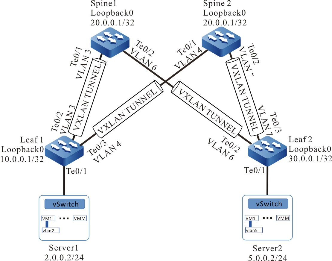
Figura 2 -4 Rede de configuração do gateway dual-active centralizado BGP EVPN VXLAN
Etapas de configuração
- Passo 1:Configure a VLAN e adicione as portas à VLAN correspondente (omitida).
- Passo 2:Configure o endereço IP da interface.
#Configure Leaf1.
Leaf1(config)#interface loopback 0Leaf1(config-if-loopback0)#ip address 10.0.0.1 255.255.255.255Leaf1(config-if-loopback0)#exitLeaf1(config)#interface vlan 3Leaf1(config-if-vlan3)#ip address 3.0.0.1 255.255.255.0Leaf1(config-if-vlan3)#exitLeaf1(config)#interface vlan 4Leaf1(config-if-vlan4)#ip address 4.0.0.1 255.255.255.0Leaf1(config-if-vlan4)#exit
#Configure Leaf2.
Leaf2(config)#interface loopback 0Leaf2(config-if-loopback0)#ip address 30.0.0.1 255.255.255.255Leaf2(config-if-loopback0)#exitLeaf2(config)#interface vlan 6Leaf2(config-if-vlan6)#ip address 6.0.0.2 255.255.255.0Leaf2(config-if-vlan6)#exitLeaf2(config)#interface vlan 7Leaf2(config-if-vlan7)#ip address 7.0.0.2 255.255.255.0Leaf2(config-if-vlan7)#exit
#Configure Spine1.
Spine1(config)#interface loopback 0Spine1(config-if-loopback0)#ip address 20.0.0.1 255.255.255.255Spine1(config-if-loopback0)#exitSpine1(config)#interface loopback 1Spine1(config-if-loopback1)#ip address 20.0.1.1 255.255.255.255Spine1(config-if-loopback1)#exitSpine1(config)#interface vlan 3Spine1(config-if-vlan3)#ip address 3.0.0.2 255.255.255.0Spine1(config-if-vlan3)#exitSpine1(config)#interface vlan 6Spine1(config-if-vlan6)#ip address 6.0.0.2 255.255.255.0Spine1(config-if-vlan6)#exit
#Configurar Spine2.
Spine2(config)#interface loopback 0Spine2(config-if-loopback0)#ip address 20.0.0.1 255.255.255.255Spine2(config-if-loopback0)#exitSpine2(config)#interface loopback 1Spine2(config-if-loopback1)#ip address 20.0.2.1 255.255.255.255Spine2(config-if-loopback1)#exitSpine2(config)#interface vlan 4Spine2(config-if-vlan4)#ip address 4.0.0.2 255.255.255.0Spine2(config-if-vlan4)#exitSpine2(config)#interface vlan 7Spine2(config-if-vlan7)#ip address 7.0.0.2 255.255.255.0Spine2(config-if-vlan7)#exit
- Passo 3:Configure o OSPF, tornando a rota de Loopback entre dispositivos alcançável.
#Configure Leaf1.
Leaf1#configure terminalLeaf1(config)#router ospf 100Leaf1(config-ospf)#network 10.0.0.1 0.0.0.0 area 0Leaf1(config-ospf)#network 3.0.0.0 0.0.0.255 area 0Leaf1(config-ospf)#network 4.0.0.0 0.0.0.255 area 0Leaf1(config-ospf)#exit
#F ou a configuração de Leaf2, Spine1 e Spine2, consulte Leaf1.
#Visualize a tabela de rotas de Leaf1.
Leaf1#show ip routeCodes: C - connected, S - static, R - RIP, O - OSPF, OE-OSPF External, M - ManagementD - Redirect, E - IRMP, EX - IRMP external, o - SNSP, B - BGP, i-ISISGateway of last resort is not setC 3.0.0.0/24 is directly connected, 02:47:02, vlan3C 4.0.0.0/24 is directly connected, 02:46:43, vlan4O 6.0.0.0/24 [110/2] via 3.0.0.2, 02:32:02, vlan3O 7.0.0.0/24 [110/2] via 4.0.0.2, 02:31:22, vlan4C 127.0.0.0/8 is directly connected, 21:16:50, lo0C 10.0.0.1/32 is directly connected, 02:51:55, loopback0O 20.0.0.1/32 [110/2] via 3.0.0.2, 02:32:02, vlan3[110/2] via 4.0.0.2, 02:31:32, vlan4O 20.0.1.1/32 [110/2] via 3.0.0.2, 01:51:02, vlan3O 20.0.2.1/32 [110/2] via 4.0.0.2, 01:53:11, vlan4O 30.0.0.1/32 [110/3] via 3.0.0.2, 02:32:02, vlan3[110/3] via 4.0.0.2, 02:31:22, vlan4
Você pode ver que Leaf1 aprendeu a rota da porta de loopback de peer executando o protocolo OSPF.
- Passo 4:Configure o VXLAN e associe o VNID e configure o cluster de endereços EVPN para fazer com que as portas da Folha 1 e da Folha 2 se unam à VXLAN .
#Configure Leaf1.
Leaf1(config)# vxlan 100Leaf1(config-vxlan-100)#vxlan vnid 100Leaf1(config-vxlan-100)#address-family evpnLeaf1(config-vxlan-evpn)#rd 100:1Leaf1(config-vxlan-evpn)#route-target both 100:1Leaf1(config-vxlan-evpn)#exitLeaf1(config-vxlan-100)#exitLeaf1(config)# interface tengigabitethernet 0/1Leaf1(config-if-tengigabitethernet0/1)# vxlan 100 encapsulation vlan 2Leaf1(config-if-tengigabitethernet0/1)#exit
#Configure Leaf2.
Leaf2(config)# vxlan 200Leaf2(config-vxlan-200)# vxlan vnid 200Leaf2(config-vxlan-200)#address-family evpnLeaf2(config-vxlan-evpn)#rd 200:1Leaf2(config-vxlan-evpn)#route-target both 200:1Leaf2(config-vxlan-evpn)#exitLeaf2(config-vxlan-200)#exitLeaf2(config)# interface tengigabitethernet 0/1Leaf2(config-if-tengigabitethernet0/1)# vxlan 200 encapsulation vlan 5Leaf2(config-if-tengigabitethernet0/1)#exit
#Configure Spine1.
Spine1(config)# vxlan 100Spine1(config-vxlan-100)#vxlan vnid 100Spine1(config-vxlan-100)#address-family evpnSpine1(config-vxlan-evpn)#rd 100:1Spine1(config-vxlan-evpn)#route-target both 100:1Spine1(config-vxlan-evpn)#exitSpine1(config-vxlan-100)#exitSpine1(config)# vxlan 200Spine1(config-vxlan-200)# vxlan vnid 200Spine1(config-vxlan-200)#address-family evpnSpine1(config-vxlan-evpn)#rd 200:1Spine1(config-vxlan-evpn)#route-target both 200:1Spine1(config-vxlan-evpn)#exitSpine1(config-vxlan-200)#exit
#Configurar Spine2.
Spine2(config)# vxlan 100Spine2(config-vxlan-100)#vxlan vnid 100Spine2(config-vxlan-100)#address-family evpnSpine2(config-vxlan-evpn)#rd 100:1Spine2(config-vxlan-evpn)#route-target both 100:1Spine2(config-vxlan-evpn)#exitSpine2(config-vxlan-100)#exitSpine2(config)# vxlan 200Spine2(config-vxlan-200)# vxlan vnid 200Spine2(config-vxlan-200)#address-family evpnSpine2(config-vxlan-evpn)#rd 200:1Spine2(config-vxlan-evpn)#route-target both 200:1Spine2(config-vxlan-evpn)#exitSpine2(config-vxlan-200)#exit
# Visualize as informações de VXLAN de Leaf1..
Leaf1#show vxlan configvxlan 100vxlan vnid 100address-family evpnrd 100:1route-target import 100:1route-target export 100:1exitexitLeaf1#show running-config interface te0/1interface tengigabitethernet0/1switchport mode trunkswitchport trunk allowed vlan add 2switchport trunk pvid vlan 1vxlan 100 encapsulation vlan 2exit
# Visualize as informações de VXLAN de Leaf2..
Leaf2#show vxlan configvxlan 200vxlan vnid 200address-family evpnrd 200:1route-target import 200:1route-target export 200:1exitexitLeaf2#show running-config interface te0/1interface tengigabitethernet0/1switchport mode trunkswitchport trunk allowed vlan add 5switchport trunk pvid vlan 1vxlan 200 encapsulation vlan 5exit
# Veja as informações de VXLAN do Spine1..
Spine1#show vxlan configvxlan 100vxlan vnid 100address-family evpnrd 100:1route-target import 100:1route-target export 100:1exitexitvxlan 200vxlan vnid 200address-family evpnrd 200:1route-target import 200:1route-target export 200:1exitexit
# Visualize as informações de VXLAN do Spine2.
Spine2#show vxlan configvxlan 100vxlan vnid 100address-family evpnrd 100:1route-target import 100:1route-target export 100:1exitexitvxlan 200vxlan vnid 200address-family evpnrd 200:1route-target import 200:1route-target export 200:1exitexit
- Passo 5:Configurar BGP.
#Configure Leaf1.
Configure o peer IBGP com Spine1 e Spine2 e ative o recurso de notificação na família de endereços EVPN .
Leaf1(config)#router bgp 100Leaf1(config-bgp)#neighbor 20.0.1.1 remote-as 100Leaf1(config-bgp)#neighbor 20.0.1.1 update-source loopback0Leaf1(config-bgp)#neighbor 20.0.2.1 remote-as 100Leaf1(config-bgp)#neighbor 20.0.1.1 update-source loopback0Leaf1(config-bgp)#address-family l2vpn evpnLeaf1(config-bgp-af)#neighbor 20.0.1.1 activateLeaf1(config-bgp-af)#neighbor 20.0.2.1 activateLeaf1(config-bgp-af)#exit-address-familyLeaf1(config-bgp)#exit
#Configure Spine1.
Configure o peer IBGP com Leaf1 e Leaf2 e ative o recurso de notificação e o cliente refletor na família de endereços EVPN .
Spine1(config)#router bgp 100Spine1(config-bgp)#neighbor 10.0.0.1 remote-as 100Spine1(config-bgp)#neighbor 10.0.0.1 update-source loopback1Spine1(config-bgp)#neighbor 30.0.0.1 remote-as 100Spine1(config-bgp)#neighbor 30.0.0.1 update-source loopback1Spine1(config-bgp)#address-family l2vpn evpnSpine1(config-bgp-af)#neighbor 10.0.0.1 activateSpine1(config-bgp-af)#neighbor 10.0.0.1 route-reflector-clientSpine1(config-bgp-af)#neighbor 30.0.0.1 activateSpine1(config-bgp-af)#neighbor 30.0.0.1 route-reflector-clientSpine1(config-bgp-af)#exit-address-familySpine1(config-bgp)#exit
#Configure Leaf2 para estabelecer o peer IBGP com Spine1 e Spine2 e ative a capacidade de notificação na família de endereços EVPN . Para a configuração de Leaf2, consulte Leaf1.
#Configure o Spine para estabelecer o peer IBGP com Leaf1 e Leaf2 e ative o recurso de notificação na família de endereços EVPN . Para a configuração do Spine2, consulte Spine1.
# Visualize o vizinho BGP EVPN de Leaf1 .
Leaf1#show bgp l2vpn evpn summaryBGP router identifier 10.0.0.1, local AS number 100BGP table version is 11 BGP AS-PATH entries0 BGP community entriesNeighbor V AS MsgRcvd MsgSent TblVer InQ OutQ Up/Down State/PfxRcd20.0.1.1 4 100 12 12 1 0 0 00:09:05 020.0.2.1 4 100 2 2 1 0 0 00:00:21 0Total number of neighbors 2
# Visualize o vizinho BGP EVPN de Spine1 .
Spine1#show bgp l2vpn evpn summaryBGP router identifier 20.0.1.1, local AS number 100BGP table version is 11 BGP AS-PATH entries0 BGP community entriesNeighbor V AS MsgRcvd MsgSent TblVer InQ OutQ Up/Down State/PfxRcd10.0.0.1 4 100 12 12 1 0 0 00:09:17 030.0.0.1 4 100 3 3 1 0 0 00:01:14 0Total number of neighbors 2
- Passo 6:Configurar a interface NVE e a VM para acionar o ARP de aprendizado.
#Configurar a interface NVE de Leaf1, e configurar a VXLAN correspondente para usar o protocolo BGP para configurar o túnel VXLAN dinamicamente.
Leaf1(config)#interface nve 1Leaf1(config-if-nve1)#source 10.0.0.1Leaf1(config-if-nve1)#vxlan 100 ingress-replication protocol bgpLeaf1(config-if-nve1)#exit
#Configure a interface NVE do Leaf2 e configure a VXLAN correspondente para usar o protocolo BGP para configurar o túnel VXLAN dinamicamente.
Leaf2(config)#interface nve 1Leaf2(config-if-nve1)#source 30.0.0.1Leaf2(config-if-nve1)#vxlan 200 ingress-replication protocol bgpLeaf2(config-if-nve1)#exit
#Configurar a interface NVE do Spine1 e configurar o VXLAN correspondente para usar o protocolo BGP para configurar o túnel VXLAN dinamicamente.
Spine1(config)#interface nve 1Spine1(config-if-nve1)#source 20.0.0.1Spine1(config-if-nve1)#vxlan 100,200 ingress-replication protocol bgpSpine1(config-if-nve1)#exit
#Configurar a interface NVE do Spine2 e configurar a VXLAN correspondente para usar o protocolo BGP para configurar o túnel VXLAN dinamicamente.
Spine2(config)#interface nve 1Spine2(config-if-nve1)#source 20.0.0.1Spine2(config-if-nve1)#vxlan 100,200 ingress-replication protocol bgpSpine2(config-if-nve1)#exit
# VM1 no Server1 e VM1 no Server2 pingam os endereços inexistentes do mesmo segmento de rede, respectivamente.
- Passo 7:Spine1 e Spine2, crie o gateway VXLAN L3.
#On Spine1, crie o gateway VXLAN L3.
Spine1(config)#interface vxlan 100Spine1(config-if-vxlan100)#ip address 2.0.0.1 24Spine1(config-if-vxlan100)#mac-address 0000.5e00.0101Spine1(config-if-vxlan100)#exitSpine1(config)#int vxlan 200Spine1(config-if-vxlan200)#ip address 5.0.0.1 24Spine1(config-if-vxlan200)#mac-address 0000.5e00.0102Spine1(config-if-vxlan200)#exit
# No Spine2 , crie o gateway VXLAN L3.
Spine2(config)#interface vxlan 100Spine2(config-if-vxlan100)#ip address 2.0.0.1 24Spine2(config-if-vxlan100)#mac-address 0000.5e00.0101Spine2(config-if-vxlan100)#exitSpine2(config)#int vxlan 200Spine2(config-if-vxlan200)#ip address 5.0.0.1 24Spine2(config-if-vxlan200)#mac-address 0000.5e00.0102Spine2(config-if-vxlan200)#exit
#Veja a interface VXLAN e a tabela de rotas do Spine1.
Spine1#show interface vxlan 100vxlan100:line protocol is upFlags: (0xc008063) BROADCAST MULTICAST ARP RUNNINGType: ETHERNET_CSMACDInternet address: 2.0.0.1/24Broadcast address: 2.0.0.255Metric: 0, MTU: 1500, BW: 100000 Kbps, DLY: 100 usec, VRF: globalReliability 255/255, Txload 1/255, Rxload 1/255Ethernet address is 0000.5e00.01015 minutes input rate 0 bits/sec, 0 packets/sec5 minutes output rate 0 bits/sec, 0 packets/sec0 packets received; 1 packets sent0 multicast packets received1 multicast packets sent0 input errors; 0 output errors0 collisions; 0 droppedUnknown protocol 0Spine1#show interface vxlan 200vxlan200:line protocol is upFlags: (0xc008063) BROADCAST MULTICAST ARP RUNNINGType: ETHERNET_CSMACDInternet address: 5.0.0.1/24Broadcast address: 5.0.0.255Metric: 0, MTU: 1500, BW: 100000 Kbps, DLY: 100 usec, VRF: globalReliability 255/255, Txload 1/255, Rxload 1/255Ethernet address is 0000.5e00.01025 minutes input rate 0 bits/sec, 0 packets/sec5 minutes output rate 0 bits/sec, 0 packets/sec0 packets received; 1 packets sent0 multicast packets received1 multicast packets sent0 input errors; 0 output errors0 collisions; 0 droppedUnknown protocol 0Spine1#show ip routeCodes: C - connected, S - static, R - RIP, O - OSPF, OE-OSPF External, M - ManagementD - Redirect, E - IRMP, EX - IRMP external, o - SNSP, B - BGP, i-ISISGateway of last resort is not setC 2.0.0.0/24 is directly connected, 00:31:28, vxlan100C 3.0.0.0/24 is directly connected, 04:05:05, vlan3O 4.0.0.0/24 [110/2] via 3.0.0.1, 03:47:46, vlan3C 5.0.0.0/24 is directly connected, 00:04:32, vxlan200C 6.0.0.0/24 is directly connected, 04:04:53, vlan6O 7.0.0.0/24 [110/2] via 6.0.0.1, 03:47:35, vlan6C 127.0.0.0/8 is directly connected, 3d:19:46:04, lo0O 10.0.0.1/32 [110/2] via 3.0.0.1, 03:52:27, vlan3C 20.0.0.1/32 is directly connected, 04:05:42, loopback0C 20.0.1.1/32 is directly connected, 03:07:49, loopback1O 20.0.2.1/32 [110/3] via 3.0.0.1, 03:09:24, vlan3[110/3] via 6.0.0.1, 03:09:24, vlan6O 30.0.0.1/32 [110/2] via 6.0.0.1, 03:52:27, vlan6
#Veja a interface VXLAN e a tabela de rotas do Spine2.
Spine2#show interface vxlan 100vxlan100:line protocol is upFlags: (0xc008063) BROADCAST MULTICAST ARP RUNNINGType: ETHERNET_CSMACDInternet address: 2.0.0.1/24Broadcast address: 2.0.0.255Metric: 0, MTU: 1500, BW: 100000 Kbps, DLY: 100 usec, VRF: globalReliability 255/255, Txload 1/255, Rxload 1/255Ethernet address is 0000.5e00.01015 minutes input rate 0 bits/sec, 0 packets/sec5 minutes output rate 0 bits/sec, 0 packets/sec0 packets received; 1 packets sent0 multicast packets received1 multicast packets sent0 input errors; 0 output errors0 collisions; 0 droppedUnknown protocol 0Spine2#show interface vxlan 200vxlan200:line protocol is upFlags: (0xc008063) BROADCAST MULTICAST ARP RUNNINGType: ETHERNET_CSMACDInternet address: 5.0.0.1/24Broadcast address: 5.0.0.255Metric: 0, MTU: 1500, BW: 100000 Kbps, DLY: 100 usec, VRF: globalReliability 255/255, Txload 1/255, Rxload 1/255Ethernet address is 0000.5e00.01025 minutes input rate 0 bits/sec, 0 packets/sec5 minutes output rate 0 bits/sec, 0 packets/sec0 packets received; 1 packets sent0 multicast packets received1 multicast packets sent0 input errors; 0 output errors0 collisions; 0 droppedUnknown protocol 0Spine2#show ip routeCodes: C - connected, S - static, R - RIP, O - OSPF, OE-OSPF External, M - ManagementD - Redirect, E - IRMP, EX - IRMP external, o - SNSP, B - BGP, i-ISISGateway of last resort is not setC 2.0.0.0/24 is directly connected, 02:35:05, vxlan100O 3.0.0.0/24 [110/2] via 4.0.0.1, 00:45:30, vlan4C 4.0.0.0/24 is directly connected, 06:08:19, vlan4C 5.0.0.0/24 is directly connected, 02:08:45, vxlan200O 6.0.0.0/24 [110/2] via 7.0.0.1, 05:51:24, vlan7C 7.0.0.0/24 is directly connected, 06:08:01, vlan7C 127.0.0.0/8 is directly connected, 1d:00:42:19, lo0O 10.0.0.1/32 [110/2] via 4.0.0.1, 05:51:24, vlan4C 20.0.0.1/32 is directly connected, 06:09:57, loopback0O 20.0.1.1/32 [110/3] via 7.0.0.1, 05:11:01, vlan7[110/3] via 4.0.0.1, 00:00:21, vlan4C 20.0.2.1/32 is directly connected, 05:13:31, loopback1O 30.0.0.1/32 [110/2] via 7.0.0.1, 05:51:24, vlan7
- Passo 8:a rota BGP EVPN e as informações da sessão VXLAN.
#Visualize as informações de rota BGP EVPN de Leaf1.
Leaf1#show bgp l2vpn evpn all all-typeBGP local router ID is 10.0.0.1Status codes: s suppressed, d damped, h history, * valid, > best, i - internal,S StaleOrigin codes: i - IGP, e - EGP, ? - incompleteEVPN Information for Route Distinguisher:100:1MAC/IP Advertisement Routes:Network(ETID:MAC:IP) Next Hop Metric LocPrf Weight Path[B]*>i0:48:0000.5e00.0101:0:0.0.0.0/96 20.0.0.1 0 100 0 i[B]* i 20.0.0.1 0 100 0 i[B]*> 0:48:0010.9400.0002:0:0.0.0.0/96 0.0.0.0 0 32768 i[B]*>i0:48:0000.5e00.0101:32:2.0.0.1/128 20.0.0.1 0 100 0 i[B]* i 20.0.0.1 0 100 0 i[B]*> 0:48:0010.9400.0002:32:2.0.0.2/128 0.0.0.0 0 32768 iInclusive Multicast Ethernet Tag Routes:Network(Originating IP Addr) Next Hop Metric LocPrf Weight Path[B]*> 0:32:10.0.0.1/72 0.0.0.0 0 32768 i[B]*>i0:32:20.0.0.1/72 20.0.0.1 0 100 0 i[B]* i 20.0.0.1 0 100 0 i
#Visualize as informações de rota BGP EVPN de Leaf2.
Leaf2#show bgp l2vpn evpn all all-typeBGP local router ID is 30.0.0.1Status codes: s suppressed, d damped, h history, * valid, > best, i - internal,S StaleOrigin codes: i - IGP, e - EGP, ? - incompleteEVPN Information for Route Distinguisher:200:1MAC/IP Advertisement Routes:Network(ETID:MAC:IP) Next Hop Metric LocPrf Weight Path[B]*>i0:48:0000.5e00.0102:0:0.0.0.0/96 20.0.0.1 0 100 0 i[B]* i 20.0.0.1 0 100 0 i[B]*> 0:48:0010.9400.0001:0:0.0.0.0/96 0.0.0.0 0 32768 i[B]*>i0:48:0000.5e00.0102:32:5.0.0.1/128 20.0.0.1 0 100 0 i[B]* i 20.0.0.1 0 100 0 i[B]*> 0:48:0010.9400.0001:32:5.0.0.2/128 0.0.0.0 0 32768 iInclusive Multicast Ethernet Tag Routes:Network(Originating IP Addr) Next Hop Metric LocPrf Weight Path[B]*>i0:32:20.0.0.1/72 20.0.0.1 0 100 0 i[B]* i 20.0.0.1 0 100 0 i[B]*> 0:32:30.0.0.1/72 0.0.0.0 0 32768 i
#Visualize as informações de rota BGP EVPN de Spine1.
Spine1#show bgp l2vpn evpn all all-typeBGP local router ID is 20.0.1.1Status codes: s suppressed, d damped, h history, * valid, > best, i - internal,S StaleOrigin codes: i - IGP, e - EGP, ? - incompleteEVPN Information for Route Distinguisher:100:1MAC/IP Advertisement Routes:Network(ETID:MAC:IP) Next Hop Metric LocPrf Weight Path[B]*> 0:48:0000.5e00.0101:0:0.0.0.0/96 0.0.0.0 0 32768 i[B]*>i0:48:0010.9400.0002:0:0.0.0.0/96 10.0.0.1 0 100 0 i[B]*> 0:48:0000.5e00.0101:32:2.0.0.1/128 0.0.0.0 0 32768 i[B]*>i0:48:0010.9400.0002:32:2.0.0.2/128 10.0.0.1 0 100 0 iInclusive Multicast Ethernet Tag Routes:Network(Originating IP Addr) Next Hop Metric LocPrf Weight Path[B]*>i0:32:10.0.0.1/72 10.0.0.1 0 100 0 i[B]*> 0:32:20.0.0.1/72 0.0.0.0 0 32768 iEVPN Information for Route Distinguisher:200:1MAC/IP Advertisement Routes:Network(ETID:MAC:IP) Next Hop Metric LocPrf Weight Path[B]*> 0:48:0000.5e00.0102:0:0.0.0.0/96 0.0.0.0 0 32768 i[B]*>i0:48:0010.9400.0001:0:0.0.0.0/96 30.0.0.1 0 100 0 i[B]*> 0:48:0000.5e00.0102:32:5.0.0.1/128 0.0.0.0 0 32768 i[B]*>i0:48:0010.9400.0001:32:5.0.0.2/128 30.0.0.1 0 100 0 iInclusive Multicast Ethernet Tag Routes:Network(Originating IP Addr) Next Hop Metric LocPrf Weight Path[B]*> 0:32:20.0.0.1/72 0.0.0.0 0 32768 i[B]*>i0:32:30.0.0.1/72 30.0.0.1 0 100 0 i
#Veja as informações do túnel e as informações da sessão VXLAN de Leaf1.
Leaf1# show vxlan tunnelNumber of vxlan tunnel: 1---- ---------- ------------------- ------------------- ----------NO. TunnelID Source Destination State---- ---------- ------------------- ------------------- ----------1 32768 10.0.0.1 20.0.0.1 upLeaf1#show vxlan sessionNumber of vxlan session: 1---- ---------- ---------- ---------- ------------------- ------------------- ----------NO. VXLAN-ID SessionID TunnelID Source Destination State---- ---------- ---------- ---------- ------------------- ------------------- ----------1 100 32768 32768 10.0.0.1 20.0.0.1 upLeaf1#show vxlan session 20.0.0.1vxlan session 32768state: upsource IP: 10.0.0.1destination IP: 20.0.0.1source mac: 0001.7a91.2de8destination mac: 0001.7a21.8203interface: vlan4switchport: tengigabitethernet0/3source mac: 0001.7a91.2de8destination mac: 0001.7a21.81e7interface: vlan3switchport: tengigabitethernet0/2vxlan list: 100vxlan unicast list: 100vxlan multicast list: 100
Pode ser visto que Leaf1 estabelece sessões dinâmicas de unicast e multicast VXLAN com Spine1 e Spine2.
#Visualize as informações do túnel e as informações da sessão VXLAN do Leaf2.
Leaf2# show vxlan tunnelNumber of vxlan tunnel: 1---- ---------- ------------------- ------------------- ----------NO. TunnelID Source Destination State---- ---------- ------------------- ------------------- ----------1 32768 30.0.0.1 20.0.0.1 upLeaf2#show vxlan sessionNumber of vxlan session: 1---- ---------- ---------- ---------- ------------------- ------------------- ----------NO. VXLAN-ID SessionID TunnelID Source Destination State---- ---------- ---------- ---------- ------------------- ------------------- ----------1 200 32768 32768 30.0.0.1 20.0.0.1 upLeaf2#show vxlan session 20.0.0.1vxlan session 32768state: upsource IP: 30.0.0.1destination IP: 20.0.0.1source mac: 0001.7a00.5278destination mac: 0001.7a21.81e7interface: vlan6switchport: tengigabitethernet0/2source mac: 0001.7a00.5278destination mac: 0001.7a21.8203interface: vlan7switchport: tengigabitethernet0/3vxlan list: 200vxlan unicast list: 200vxlan multicast list: 200
Pode ser visto que Leaf2 estabelece sessões dinâmicas de unicast e multicast VXLAN com Spine1 e Spine2.
- Passo 9:Confira o resultado.
# No Server1 e Server2, configure o gateway.
#No Server1, ping Server2.
C:\Documents and Settings\ Server 1> ping 5.0.0.2Pinging 5.0.0.2 with 32 bytes of data:Reply from 5.0.0.2: bytes=32 time<1ms TTL=255Reply from 5.0.0.2: bytes=32 time<1ms TTL=255Reply from 5.0.0.2: bytes=32 time<1ms TTL=255Reply from 5.0.0.2: bytes=32 time<1ms TTL=255Ping statistics for 5.0.0.2:Packets: Sent = 4, Received = 4, Lost = 0 (0% loss),Approximate round trip times in milli-seconds:Minimum = 0ms, Maximum = 0ms, Average = 0m
Server1 e Server2 podem cruzar a rede L3 para realizar a intercomunicação.
Configurar BGP EVPN VXLAN Gateway distribuído
Requisitos de rede
- Crie instâncias VXLAN em Leaf1, Leaf2, Spine1 e Spine2, respectivamente
- Leaf1, Spine1 e Leaf2 conectam a rota EVPN através do MP-IBGP . Folha1 e Leaf2 criam o túnel IBGP EVPN VXLAN; crie a instância VRF e o gateway distribuído VXLAN em Leaf1 e Leaf2 para realizar o interfuncionamento entre server1 e server3 no mesmo segmento de rede e server2 e server3 em diferentes segmentos de rede.
- Na família de endereços BGP VRF em Leaf1 e Leaf2, habilite a importação da rota para a família de endereços EVPN, realizando a intercomunicação entre a rede VXLAN e a rede IP comum
Topologia de rede

Figura 2 -5 Rede de configuração do gateway distribuído BGP EVPN VXLAN
Etapas de configuração
- Passo 1:Configure a VLAN e adicione as portas à VLAN correspondente (omitida).
- Passo 2:Configure o endereço IP da interface.
#Configure Leaf1.
Leaf1(config)#interface loopback 0Leaf1(config-if-loopback0)#ip address 10.0.0.1 255.255.255.255Leaf1(config-if-loopback0)#exitLeaf1(config)#interface loopback 1Leaf1(config-if-loopback1)#ip address 10.0.1.1 255.255.255.255Leaf1(config-if-loopback1)#exitLeaf1(config)#interface vlan 3Leaf1(config-if-vlan3)#ip address 2.0.0.1 255.255.255.0Leaf1(config-if-vlan3)#exit
#Configure Spine1.
Spine1(config)#interface loopback 0Spine1(config-if-loopback0)#ip address 20.0.0.1 255.255.255.255Spine1(config-if-loopback0)#exitSpine1(config)#interface loopback 1Spine1(config-if-loopback1)#ip address 20.0.1.1 255.255.255.255Spine1(config-if-loopback1)#exitSpine1(config)#interface vlan 3Spine1(config-if-vlan3)#ip address 2.0.0.2 255.255.255.0Spine1(config-if-vlan3)#exitSpine1(config)#interface vlan 4Spine1(config-if-vlan4)#ip address 3.0.0.1 255.255.255.0Spine1(config-if-vlan4)#exit
#Configure Leaf2.
Leaf2(config)#interface loopback 0Leaf2(config-if-loopback0)#ip address 30.0.0.1 255.255.255.255Leaf2(config-if-loopback0)#exitLeaf2(config)#interface loopback 1Leaf2(config-if-loopback1)#ip address 30.0.1.1 255.255.255.255Leaf2(config-if-loopback1)#exitLeaf2(config)#interface vlan 4Leaf2(config-if-vlan4)#ip address 3.0.0.2 255.255.255.0Leaf2(config-if-vlan4)#exit
- Passo 3:Configure o OSPF, tornando a rota de Loopback entre dispositivos alcançável.
#Configure Leaf1.
Leaf1#configure terminalLeaf1(config)#router ospf 100Leaf1(config-ospf)#network 10.0.0.1 0.0.0.0 area 0Leaf1(config-ospf)#network 10.0.1.1 0.0.0.0 area 0Leaf1(config-ospf)#network 2.0.0.0 0.0.0.255 area 0Leaf1(config-ospf)#exit
#Configure Spine1.
Spine1#configure terminalSpine1(config)#router ospf 100Spine1(config-ospf)#network 20.0.0.1 0.0.0.0 area 0Spine1(config-ospf)#network 20.0.1.1 0.0.0.0 area 0Spine1(config-ospf)#network 2.0.0.0 0.0.0.255 area 0Spine1(config-ospf)#network 3.0.0.0 0.0.0.255 area 0Spine1(config-ospf)#exit
#Configure Leaf2.
Leaf2#configure terminalLeaf2(config)#router ospf 100Leaf2(config-ospf)#network 30.0.0.1 0.0.0.0 area 0Leaf2(config-ospf)#network 30.0.1.1 0.0.0.0 area 0Leaf2(config-ospf)#network 3.0.0.0 0.0.0.255 area 0Leaf2(config-ospf)#exit
#Visualize a tabela de rotas da Folha 1.
Leaf1#show ip routeCodes: C - connected, S - static, R - RIP, O - OSPF, OE-OSPF External, M - ManagementD - Redirect, E - IRMP, EX - IRMP external, o - SNSP, B - BGP, i-ISISGateway of last resort is not setC 2.0.0.0/24 is directly connected, 00:56:51, vlan3O 3.0.0.0/24 [110/2] via 2.0.0.2, 00:56:00, vlan3C 10.0.1.0/24 is directly connected, 00:08:30, loopback1C 127.0.0.0/8 is directly connected, 3d:03:23:29, lo0C 10.0.0.1/32 is directly connected, 00:56:51, loopback0O 20.0.0.1/32 [110/2] via 2.0.0.2, 00:56:00, vlan3O 20.0.1.1/32 [110/2] via 2.0.0.2, 00:05:22, vlan3O 30.0.0.1/32 [110/3] via 2.0.0.2, 00:55:52, vlan3O 30.0.1.1/32 [110/3] via 2.0.0.2, 00:05:44, vlan3
#Visualize a tabela de rotas do Spine 1..
Spine1#show ip routeCodes: C - connected, S - static, R - RIP, O - OSPF, OE-OSPF External, M - ManagementD - Redirect, E - IRMP, EX - IRMP external, o - SNSP, B - BGP, i-ISISGateway of last resort is not setC 2.0.0.0/24 is directly connected, 01:01:05, vlan3C 3.0.0.0/24 is directly connected, 01:01:05, vlan4C 20.0.1.0/24 is directly connected, 00:12:40, loopback1C 127.0.0.0/8 is directly connected, 1w4d:09:22:41, lo0O 10.0.0.1/32 [110/2] via 2.0.0.1, 01:00:21, vlan3O 10.0.1.1/32 [110/2] via 2.0.0.1, 00:08:04, vlan3C 20.0.0.1/32 is directly connected, 01:01:05, loopback0O 30.0.0.1/32 [110/2] via 3.0.0.2, 01:00:13, vlan4O 30.0.1.1/32 [110/2] via 3.0.0.2, 00:10:05, vlan4
#Visualize a tabela de rotas do Leaf 2..
Leaf2#show ip routeCodes: C - connected, S - static, R - RIP, O - OSPF, OE-OSPF External, M - ManagementD - Redirect, E - IRMP, EX - IRMP external, o - SNSP, B - BGP, i-ISISGateway of last resort is not setO 2.0.0.0/24 [110/2] via 3.0.0.1, 01:04:02, vlan4C 3.0.0.0/24 is directly connected, 01:04:44, vlan4C 30.0.0.0/24 is directly connected, 01:04:44, loopback0C 30.0.1.0/24 is directly connected, 00:15:47, loopback1C 127.0.0.0/8 is directly connected, 4d:04:40:07, lo0O 10.0.0.1/32 [110/3] via 3.0.0.1, 01:04:02, vlan4O 10.0.1.1/32 [110/3] via 3.0.0.1, 00:11:49, vlan4O 20.0.0.1/32 [110/2] via 3.0.0.1, 01:04:02, vlan4O 20.0.1.1/32 [110/2] via 3.0.0.1, 00:13:28, vlan4
Você pode ver que Leaf1 , Spine1 e Leaf2 aprenderam as rotas para as portas de loopback de peer executando o protocolo OSPF.
- Passo 4:Configure VXLAN e associe VNID , e configure a família de endereços EVPN para fazer as portas de Leaf1 e Leaf2 se juntarem a VXLAN .
#Configure Leaf1 .
Leaf1(config)#vxlan 100Leaf1(config-vxlan-100)#vxlan vnid 100Leaf1(config-vxlan-100)#address-family evpnLeaf1(config-vxlan-evpn)#rd 100:1Leaf1(config-vxlan-evpn)#route-target both 100:1Leaf1(config-vxlan-evpn)#exitLeaf1(config-vxlan-100)#exitLeaf1(config)# interface tengigabitethernet 0/1Leaf1(config-if-tengigabitethernet0/1)# vxlan 100 encapsulation vlan 2Leaf1(config-if-tengigabitethernet0/1)#exitLeaf1(config)# vxlan 200Leaf1(config-vxlan-200)#vxlan vnid 200Leaf1(config-vxlan-200)#address-family evpnLeaf1(config-vxlan-evpn)#rd 200:1Leaf1(config-vxlan-evpn)#route-target both 200:1Leaf1(config-vxlan-evpn)#exitLeaf1(config-vxlan-200)#exitLeaf1(config)# interface tengigabitethernet 0/3Leaf1(config-if-tengigabitethernet0/3)# vxlan 200 encapsulation vlan 5Leaf1(config-if-tengigabitethernet0/3)#exit
#Configure Spine1 .
Spine1(config)#vxlan 100Spine1(config-vxlan-100)#vxlan vnid 100Spine1(config-vxlan-100)#address-family evpnSpine1(config-vxlan-evpn)#rd 100:1Spine1(config-vxlan-evpn)#route-target both 100:1Spine1(config-vxlan-evpn)#exitSpine1(config-vxlan-100)#exitSpine1(config)#vxlan 200Spine1(config-vxlan-200)#vxlan vnid 200Spine1(config-vxlan-200)#address-family evpnSpine1(config-vxlan-evpn)#rd 200:1Spine1(config-vxlan-evpn)#route-target both 200:1Spine1(config-vxlan-evpn)#exitSpine1(config-vxlan-200)#exit
#Configure Leaf2 .
Leaf2(config)#vxlan 100Leaf2(config-vxlan-100)#vxlan vnid 100Leaf2(config-vxlan-100)#address-family evpnLeaf2(config-vxlan-evpn)#rd 100:1Leaf2(config-vxlan-evpn)#route-target both 100:1Leaf2(config-vxlan-evpn)#exitLeaf2(config-vxlan-100)#exitLeaf2(config)# interface tengigabitethernet 0/1Leaf2(config-if-tengigabitethernet0/1)# vxlan 100 encapsulation vlan 2Leaf2(config-if-tengigabitethernet0/1)#exit
# Visualize as informações de VXLAN de Leaf1..
Leaf1#show vxlan configvxlan 100vxlan vnid 100address-family evpnrd 100:1route-target import 100:1route-target export 100:1exitexitvxlan 200vxlan vnid 200address-family evpnrd 200:1route-target import 200:1route-target export 200:1exitexitLeaf1#show running-config interface te0/1interface tengigabitethernet0/1switchport mode trunkswitchport trunk allowed vlan add 2switchport trunk pvid vlan 1vxlan 100 encapsulation vlan 2exitLeaf1#show running-config interface te0/3interface tengigabitethernet0/3switchport mode trunkswitchport trunk allowed vlan add 5switchport trunk pvid vlan 1vxlan 200 encapsulation vlan 5exit
# Veja as informações de VXLAN do Spine1..
Spine1#show vxlan configvxlan 100vxlan vnid 100address-family evpnrd 100:1route-target import 100:1route-target export 100:1exitexitvxlan 200vxlan vnid 200address-family evpnrd 200:1route-target import 200:1route-target export 200:1exitexit
# Visualize as informações de VXLAN de Leaf2..
Leaf2#show vxlan configvxlan 100vxlan vnid 100address-family evpnrd 100:1route-target import 100:1route-target export 100:1exitexitLeaf1#show running-config interface te0/1interface tengigabitethernet0/1switchport mode trunkswitchport trunk allowed vlan add 2switchport trunk pvid vlan 1vxlan 100 encapsulation vlan 2exit
- Passo 5:Configurar BGP.
#Configure Leaf1 .
Configure o peer IBGP com Spine1 e ative o recurso de notificação na família de endereços EVPN.
Leaf1(config)#router bgp 100Leaf1(config-bgp)#neighbor 20.0.1.1 remote-as 100Leaf1(config-bgp)#neighbor 20.0.1.1 update-source loopback 1Leaf1(config-bgp)#address-family l2vpn evpnLeaf1(config-bgp-af)#neighbor 20.0.1.1 activateLeaf1(config-bgp-af)#exit-address-familyLeaf1(config-bgp)#exit
#Configure Spine1 .
Leaf1 e Leaf2 respectivamente, e ative o recurso de notificação e configure o refletor na família de endereços EVPN.
Spine1(config)#router bgp 100Spine1(config-bgp)#neighbor 10.0.1.1 remote-as 100Spine1(config-bgp)#neighbor 10.0.1.1 update-source loopback 1Spine1(config-bgp)#neighbor 30.0.1.1 remote-as 100Spine1(config-bgp)#neighbor 30.0.1.1 update-source loopback 1Spine1(config-bgp)#address-family l2vpn evpnSpine1(config-bgp-af)#neighbor 10.0.1.1 activateSpine1(config-bgp-af)#neighbor 10.0.1.1 route-reflector-clientSpine1(config-bgp-af)#neighbor 30.0.1.1 activateSpine1(config-bgp-af)#neighbor 30.0.1.1 route-reflector-clientSpine1(config-bgp-af)#exit-address-familySpine1(config-bgp)#exit
#Configure Leaf2 .
Spine1 e ative o recurso de notificação na família de endereços EVPN.
Leaf2(config)#router bgp 100Leaf2(config-bgp)#neighbor 20.0.1.1 remote-as 100Leaf2(config-bgp)#neighbor 20.0.1.1 update-source loopback 1Leaf2(config-bgp)#address-family l2vpn evpnLeaf2(config-bgp-af)#neighbor 20.0.1.1 activateLeaf2(config-bgp-af)#exit-address-familyLeaf2(config-bgp)#exit
# Visualize o vizinho BGP EVPN de Leaf1 .
Leaf1#show bgp l2vpn evpn summaryBGP router identifier 10.0.1.1, local AS number 100BGP table version is 11 BGP AS-PATH entries0 BGP community entriesNeighbor V AS MsgRcvd MsgSent TblVer InQ OutQ Up/Down State/PfxRcd20.0.1.1 4 100 2 2 1 0 0 00:00:28 0Total number of neighbors 1
# Visualize o vizinho BGP EVPN de Spine1 .
Spine1#show bgp l2vpn evpn summaryBGP router identifier 20.0.1.1, local AS number 100BGP table version is 11 BGP AS-PATH entries0 BGP community entriesNeighbor V AS MsgRcvd MsgSent TblVer InQ OutQ Up/Down State/PfxRcd10.0.1.1 4 100 3 3 1 0 0 00:01:34 030.0.1.1 4 100 2 2 1 0 0 00:00:02 0Total number of neighbors 2
# Visualize o vizinho BGP EVPN de Leaf2 .
Leaf2#show bgp l2vpn evpn summaryBGP router identifier 30.0.1.1, local AS number 100BGP table version is 11 BGP AS-PATH entries0 BGP community entriesNeighbor V AS MsgRcvd MsgSent TblVer InQ OutQ Up/Down State/PfxRcd20.0.1.1 4 100 3 3 1 0 0 00:01:10 0Total number of neighbors 1
- Passo 6:Configurar a instância VRF.
#Configure a instância VRF de Leaf1 .
Leaf1(config)#ip vrf 1Leaf1(config-vrf)#rd 100:2Leaf1(config-vrf)#l3vnid 1Leaf1(config-vrf)#address-family evpnLeaf1(config-vrf-evpn)#route-target both 100:2Leaf1(config-vrf-evpn)#exitLeaf1(config-vrf)#exit
#Configure a instância VRF de Leaf2 .
Leaf2(config)#ip vrf 1Leaf2(config-vrf)#rd 100:2Leaf2(config-vrf)#l3vnid 1Leaf2(config-vrf)#address-family evpnLeaf2(config-vrf-evpn)#route-target both 100:2Leaf2(config-vrf-evpn)#exitLeaf2(config-vrf)#exit
- Passo 7:Configurar a interface NVE.
#Configure a interface NVE de Leaf1 e configure a VXLAN correspondente para usar o protocolo BGP para configurar o túnel L2 dinamicamente.
Leaf1(config)#interface nve 1Leaf1(config-if-nve1)#source 10.0.0.1Leaf1(config-if-nve1)#vxlan 100,200 ingress-replication protocol bgpLeaf1(config-if-nve1)#exit
#Configure a interface NVE do Leaf2 e configure o VXLAN correspondente para usar o protocolo BGP para configurar o túnel L2 dinamicamente.
Leaf2(config)#interface nve 1Leaf2(config-if-nve1)#source 30.0.0.1Leaf2(config-if-nve1)#vxlan 100 ingress-replication protocol bgpLeaf2(config-if-nve1)#exit
- Passo 8:Configurar o gateway VXLAN L3 e vincular a instância VRF correspondente.
#Configure o gateway L3 de Leaf1 e vincule a instância VRF correspondente.
Leaf1(config)#interface vxlan 200Leaf1(config-if-vxlan200)#ip vrf forwarding 1Leaf1(config-if-vxlan200)#vxlan distribute-gatewayLeaf1(config-if-vxlan200)#ip address 5.0.0.1 24Leaf1(config-if-vxlan200)#exit
#Configure o gateway L3 do Leaf2 e vincule a instância VRF correspondente.
Leaf2(config)#interface vxlan 100Leaf2(config-if-vxlan100)#ip vrf forwarding 1Leaf2(config-if-vxlan100)#vxlan distribute-gatewayLeaf2(config-if-vxlan100)#ip address 1.0.0.1 24Leaf2(config-if-vxlan100)#exit
#Visualize a interface VXLAN e a tabela de rotas de Leaf1.
Leaf1#show interface vxlan 200vxlan200:line protocol is upFlags: (0xc008063) BROADCAST MULTICAST ARP RUNNINGType: ETHERNET_CSMACDInternet address: 5.0.0.1/24Broadcast address: 5.0.0.255Metric: 0, MTU: 1500, BW: 100000 Kbps, DLY: 100 usec, VRF: 1Reliability 255/255, Txload 1/255, Rxload 1/255Ethernet address is 0001.7a00.52785 minutes input rate 0 bits/sec, 0 packets/sec5 minutes output rate 0 bits/sec, 0 packets/sec94 packets received; 88 packets sent0 multicast packets received5 multicast packets sent0 input errors; 0 output errors0 collisions; 0 droppedUnknown protocol 0Leaf1#show ip route vrf 1Codes: C - connected, S - static, R - RIP, O - OSPF, OE-OSPF External, M - ManagementD - Redirect, E - IRMP, EX - IRMP external, o - SNSP, B - BGP, i-ISISGateway of last resort is not setC 5.0.0.0/24 is directly connected, 00:01:13, vxlan200
#Veja a interface VXLAN e a tabela de rotas do Leaf2.
Leaf2#show interface vxlan 100vxlan100:line protocol is upFlags: (0xc008063) BROADCAST MULTICAST ARP RUNNINGType: ETHERNET_CSMACDInternet address: 1.0.0.1/24Broadcast address: 1.0.0.255Metric: 0, MTU: 1500, BW: 100000 Kbps, DLY: 100 usec, VRF: 1Reliability 255/255, Txload 1/255, Rxload 1/255Ethernet address is 0001.7a6a.00425 minutes input rate 0 bits/sec, 0 packets/sec5 minutes output rate 0 bits/sec, 0 packets/sec0 packets received; 2 packets sent0 multicast packets received2 multicast packets sent0 input errors; 0 output errors0 collisions; 0 droppedUnknown protocol 0Leaf2#show ip route vrf 1Codes: C - connected, S - static, R - RIP, O - OSPF, OE-OSPF External, M - ManagementD - Redirect, E - IRMP, EX - IRMP external, o - SNSP, B - BGP, i-ISISGateway of last resort is not setC 1.0.0.0/24 is directly connected, 00:02:15, vxlan100
#Veja as informações do túnel e a sessão VXLAN de Leaf1.
Leaf1# show vxlan tunnelNumber of vxlan tunnel: 1---- ---------- ------------------- ------------------- ----------NO. TunnelID Source Destination State---- ---------- ------------------- ------------------- ----------1 32768 10.0.0.1 30.0.0.1 upLeaf1#show vxlan sessionNumber of vxlan session: 1---- ---------- ---------- ---------- ------------------- ------------------- ----------NO. VXLAN-ID SessionID TunnelID Source Destination State---- ---------- ---------- ---------- ------------------- ------------------- ----------1 100 32768 32768 10.0.0.1 30.0.0.1 upLeaf1#show vxlan session l3Number of vxlan session: 1---- ---------- ---------- ---------- ------------------- ------------------- ----------NO. VXLAN-ID SessionID TunnelID Source Destination State---- ---------- ---------- ---------- ------------------- ------------------- ----------1 4097 32768 32768 10.0.0.1 30.0.0.1 up
#Visualize as informações do túnel e a sessão VXLAN do Leaf2.
Leaf2# show vxlan tunnelNumber of vxlan tunnel: 1---- ---------- ------------------- ------------------- ----------NO. TunnelID Source Destination State---- ---------- ------------------- ------------------- ----------1 32768 30.0.0.1 10.0.0.1 upLeaf2#show vxlan sessionNumber of vxlan session: 1---- ---------- ---------- ---------- ------------------- ------------------- ----------NO. VXLAN-ID SessionID TunnelID Source Destination State---- ---------- ---------- ---------- ------------------- ------------------- ----------1 100 32768 32768 30.0.0.1 10.0.0.1 upLeaf2#show vxlan session l3Number of vxlan session: 1---- ---------- ---------- ---------- ------------------- ------------------- ----------NO. VXLAN-ID SessionID TunnelID Source Destination State---- ---------- ---------- ---------- ------------------- ------------------- ----------1 4097 32768 32768 30.0.0.1 10.0.0.1 up
VXLAN pode ser configurada normalmente.
- Passo 9:Configure a rota unicast VRF e habilite a função de melhorar a rota para a família de endereços EVPN sob a família de endereços BGP VRF.
#Configure Leaf1 .
Leaf1(config)#interface loopback 2Leaf1(config-if-loopback2)#ip vrf forwarding 1Leaf1(config-if-loopback2)#ip address 11.0.0.1 255.255.255.255Leaf1(config-if-loopback2)#exitLeaf1(config)#router bgp 100Leaf1(config-bgp)#address-family ipv4 vrf 1Leaf1(config-bgp-af)#advertise-l2vpn-evpnLeaf1(config-bgp-af)#network 11.0.0.1 255.255.255.255Leaf1(config-bgp-af)#exit-address-familyLeaf1(config-bgp)#exit
#Configure Leaf2 .
Leaf2(config)#interface loopback 2Leaf2(config-if-loopback2)#ip vrf forwarding 1Leaf2(config-if-loopback2)#ip address 31.0.0.1 32Leaf2(config-if-loopback2)#exitLeaf2(config)#router bgp 100Leaf2(config-bgp)#address-family ipv4 vrf 1Leaf2(config-bgp-af)#advertise-l2vpn-evpnLeaf2(config-bgp-af)#network 31.0.0.1 255.255.255.255Leaf2(config-bgp-af)#exit-address-familyLeaf2(config-bgp)#exit
# Servidor1, Server2 e Server3 enviam arp.
BGP EVPN Classe 2 e 5 e rotas unicast VRF de Leaf1.
Leaf1#show bgp l2vpn evpn all type 2BGP local router ID is 10.0.1.1Status codes: s suppressed, d damped, h history, * valid, > best, i - internal,S StaleOrigin codes: i - IGP, e - EGP, ? - incompleteEVPN Information for Route Distinguisher:100:1MAC/IP Advertisement Routes:Network(ETID:MAC:IP) Next Hop Metric LocPrf Weight Path[B]*>i0:48:0001.7a6a.0042:0:0.0.0.0/96 30.0.0.1 0 100 0 i[B]*> 0:48:0010.9400.104c:0:0.0.0.0/96 0.0.0.0 0 32768 i[B]*>i0:48:0010.9400.104e:0:0.0.0.0/96 30.0.0.1 0 100 0 i[B]*>i0:48:0001.7a6a.0042:32:1.0.0.1/128 30.0.0.1 0 100 0 i[B]*> 0:48:0010.9400.104c:32:1.0.0.2/128 0.0.0.0 0 32768 i[B]*>i0:48:0010.9400.104e:32:1.0.0.3/128 30.0.0.1 0 100 0 iEVPN Information for Route Distinguisher:100:2MAC/IP Advertisement Routes:Network(ETID:MAC:IP) Next Hop Metric LocPrf Weight Path[B]*>i0:48:0001.7a6a.0042:32:1.0.0.1/128 30.0.0.1 0 100 0 i[B]*>i0:48:0010.9400.104e:32:1.0.0.3/128 30.0.0.1 0 100 0 iEVPN Information for Route Distinguisher:200:1MAC/IP Advertisement Routes:Network(ETID:MAC:IP) Next Hop Metric LocPrf Weight Path[B]*> 0:48:0001.7a00.5278:0:0.0.0.0/96 0.0.0.0 0 32768 i[B]*> 0:48:0010.9400.104d:0:0.0.0.0/96 0.0.0.0 0 32768 i[B]*> 0:48:0001.7a00.5278:32:5.0.0.1/128 0.0.0.0 0 32768 i[B]*> 0:48:0010.9400.104d:32:5.0.0.2/128 0.0.0.0 0 32768 iLeaf1#show bgp l2vpn evpn all type 5BGP local router ID is 10.0.1.1Status codes: s suppressed, d damped, h history, * valid, > best, i - internal,S StaleOrigin codes: i - IGP, e - EGP, ? - incompleteEVPN Information for Route Distinguisher:100:2IP Prefix Routes:Network(ETID:IP) Next Hop Metric LocPrf Weight Path[B]*> 0:32:11.0.0.1/72 0.0.0.0 0 32768 i[B]*>i0:32:31.0.0.1/72 30.0.0.1 0 100 0 iLeaf1#show ip route vrf 1Codes: C - connected, S - static, R - RIP, O - OSPF, OE-OSPF External, M - ManagementD - Redirect, E - IRMP, EX - IRMP external, o - SNSP, B - BGP, i-ISISGateway of last resort is not setC 5.0.0.0/24 is directly connected, 00:09:00, vxlan200B 1.0.0.1/32 [200/0] via 30.0.0.1, 00:06:31, vxlan4097B 1.0.0.3/32 [200/0] via 30.0.0.1, 00:01:48, vxlan4097C 11.0.0.1/32 is directly connected, 00:08:47, loopback2B 31.0.0.1/32 [200/0] via 30.0.0.1, 00:06:17, vxlan4097
# Veja a rota BGP EVPN Classe 2 e 5 e rotas unicast VRF de Leaf2.
Leaf2#show bgp l2vpn evpn all type 2BGP local router ID is 30.0.1.1Status codes: s suppressed, d damped, h history, * valid, > best, i - internal,S StaleOrigin codes: i - IGP, e - EGP, ? - incompleteEVPN Information for Route Distinguisher:100:1MAC/IP Advertisement Routes:Network(ETID:MAC:IP) Next Hop Metric LocPrf Weight Path[B]*> 0:48:0001.7a6a.0042:0:0.0.0.0/96 0.0.0.0 0 32768 i[B]*>i0:48:0010.9400.104c:0:0.0.0.0/96 10.0.0.1 0 100 0 i[B]*> 0:48:0010.9400.104e:0:0.0.0.0/96 0.0.0.0 0 32768 i[B]*> 0:48:0001.7a6a.0042:32:1.0.0.1/128 0.0.0.0 0 32768 i[B]*>i0:48:0010.9400.104c:32:1.0.0.2/128 10.0.0.1 0 100 0 i[B]*> 0:48:0010.9400.104e:32:1.0.0.3/128 0.0.0.0 0 32768 iEVPN Information for Route Distinguisher:100:2MAC/IP Advertisement Routes:Network(ETID:MAC:IP) Next Hop Metric LocPrf Weight Path[B]*>i0:48:0001.7a00.5278:32:5.0.0.1/128 10.0.0.1 0 100 0 i[B]*>i0:48:0010.9400.104d:32:5.0.0.2/128 10.0.0.1 0 100 0 iEVPN Information for Route Distinguisher:200:1MAC/IP Advertisement Routes:Network(ETID:MAC:IP) Next Hop Metric LocPrf Weight Path[B]*>i0:48:0001.7a00.5278:32:5.0.0.1/128 10.0.0.1 0 100 0 i[B]*>i0:48:0010.9400.104d:32:5.0.0.2/128 10.0.0.1 0 100 0 iLeaf2#show bgp l2vpn evpn all type 5BGP local router ID is 30.0.1.1Status codes: s suppressed, d damped, h history, * valid, > best, i - internal,S StaleOrigin codes: i - IGP, e - EGP, ? - incompleteEVPN Information for Route Distinguisher:100:2IP Prefix Routes:Network(ETID:IP) Next Hop Metric LocPrf Weight Path[B]*>i0:32:11.0.0.1/72 10.0.0.1 0 100 0 i[B]*> 0:32:31.0.0.1/72 0.0.0.0 0 32768 iLeaf2#Leaf2#show ip rouLeaf2#show ip route vrf 1Codes: C - connected, S - static, R - RIP, O - OSPF, OE-OSPF External, M - ManagementD - Redirect, E - IRMP, EX - IRMP external, o - SNSP, B - BGP, i-ISISGateway of last resort is not setC 1.0.0.0/24 is directly connected, 00:09:10, vxlan100B 5.0.0.1/32 [200/0] via 10.0.0.1, 00:08:31, vxlan4097B 5.0.0.2/32 [200/0] via 10.0.0.1, 00:08:31, vxlan4097B 11.0.0.1/32 [200/0] via 10.0.0.1, 00:08:31, vxlan4097C 31.0.0.1/32 is directly connected, 00:09:14, loopback2
A informação acima mostra que o dispositivo aprende a rota unicast VRF através da rota EVPN .
- Passo 10:Confira o resultado.
#On Server3, ping Server1.
C:\Documents and Settings\ Server 3> ping 1.0.0.2Pinging 1.0.0.2 with 32 bytes of data:Reply from 1.0.0.2: bytes=32 time<1ms TTL=255Reply from 1.0.0.2: bytes=32 time<1ms TTL=255Reply from 1.0.0.2: bytes=32 time<1ms TTL=255Reply from 1.0.0.2: bytes=32 time<1ms TTL=255Ping statistics for 1.0.0.2:Packets: Sent = 4, Received = 4, Lost = 0 (0% loss),Approximate round trip times in milli-seconds:Minimum = 0ms, Maximum = 0ms, Average = 0m
Pode-se ver que Server1 e Server3 podem cruzar a rede L3 entre Leaf1, Spine1 e Leaf2 para realizar a intercomunicação.
#On Server3, ping Server2.
C:\Documents and Settings\ Server 3> ping 5.0.0.2Pinging 5.0.0.2 with 32 bytes of data:Reply from 5.0.0.2: bytes=32 time<1ms TTL=255Reply from 5.0.0.2: bytes=32 time<1ms TTL=255Reply from 5.0.0.2: bytes=32 time<1ms TTL=255Reply from 5.0.0.2: bytes=32 time<1ms TTL=255Ping statistics for 5.0.0.2:Packets: Sent = 4, Received = 4, Lost = 0 (0% loss),Approximate round trip times in milli-seconds:Minimum = 0ms, Maximum = 0ms, Average = 0m
Pode-se ver que o Servidor 2 e Server3 podem cruzar a rede L3 entre Leaf1, Spine1 e Leaf2 para realizar a intercomunicação.
Configurar o BGP EVPN no Data Center Distributed Gateway
Requisitos de rede
- Execute o protocolo IGP entre Spine1, Spine2, Device1 e Devcie2 para conectar a rota.
- Execute o protocolo EBGP entre Spine1 e Spine2 para conectar a rota EVPN e execute o protocolo IBGP entre Spine1 e Leaf1, Spine2 e Leaf2 para conectar a rota EVPN.
- Como VTEP, Leaf1 e Leaf2 criam o túnel IBGP EVPN VXLAN , e criam a instância VRF e o gateway distribuído vxlan em Leaf1 e Leaf2, de modo a realizar a intercomunicação entre Server1 e Server3, Server2 e Server4 no mesmo segmento de rede, Server1 e Server4 , Server2 e Server3 nos diferentes segmentos de rede.
- Na família de endereços BGP VRF em Leaf1 e Leaf2, habilite a importação da rota para a família de endereços EVPN, de modo a realizar a intercomunicação da rede VXLAN e da rede IP comum.
Topologia de rede

Figura 2 -6 Rede de configuração do BGP EVPN no gateway distribuído do data center
Etapas de configuração
- Passo 1:Configure a VLAN e adicione as portas à VLAN correspondente (omitida).
- Passo 2:Configure o endereço IP da interface. (omitido)
- Passo 3:Configure o OSPF, tornando a rota de Loopback entre dispositivos alcançável. (omitido)
- Passo 4:Leaf1 e Leaf2, configure VXLAN e associe VNID, e configure a família de endereços EVPN, de modo a fazer com que as portas de Leaf1 e Leaf2 sejam adicionadas à VXLAN. (omitido)
- Passo 5:Configurar BGP.
#Configurar Leaf1 e Spine1, Leaf2 e Spine1 para configurar o vizinho IBGP e ativar o recurso de publicidade na família de endereços EVPN (omitido).
#Configurar Spine1 e Spine2 para configurar o vizinho EBGP e ativar o recurso de publicidade na família de endereços EVPN e configurar a função de não alterar o atributo de rota ao anunciar a rota para o vizinho (omitido).
- Passo 6:Configure a instância VRF.
#Configure a instância VRF de Leaf1 e Folha2 (omitido).
- Passo 7:Configure a interface NVE.
#Configurar a interface NVE de Leaf1 e Leaf2 e configurar a VXLAN correspondente para usar o protocolo BGP para configurar dinamicamente o túnel L2 (omitido).
- Passo 8:Leaf1 e Leaf2, configure o gateway VXLAN L3 e vincule a instância VRF correspondente (omitida).
- Passo 9:Leaf1 e Leaf2, configure a rota unicast VRF e habilite a função de importar a rota para a família de endereços EVPN (omitido).
- Passo 10:Confira o resultado.
#No Server1, ping Server3.
que Server1 e Server3 podem cruzar a rede L3 entre Leaf1, Spine1 e Leaf2 para realizar a intercomunicação.
#No Server1, ping Server4.
que Server1 e Server3 podem cruzar a rede L3 entre Leaf1, Spine1 e Leaf2 para realizar a intercomunicação.
Para todas as configurações e verificação de resultados na seção, você pode consultar o conteúdo da seção 2.3.5.
NLB
Visão geral
NLB é um recurso de balanceamento de carga de cluster de vários servidores desenvolvido pela Microsoft no Windows Server. Quando o switch está conectado ao cluster de servidor NLB, o servidor NLB requer que o switch envie o pacote cujo endereço IP de destino é o endereço IP do cluster de servidor NLB para cada servidor no cluster de servidor NLB.
Configuração da função NLB
Tabela 2 -1 Lista de configuração da função NLB
| Tarefa de configuração | |
| Configurar a função NLB | Configurar o grupo de reflexão
Configure o ARP estático para vincular o grupo de reflexão Configurar a multiporta MAC estática |
Configurar NLB
Condição de configuração
Nenhum
Configurar o ARP estático para vincular o grupo de reflexão
Tabela 2 -2 Configurar o ARP estático para ligar o grupo reflectio
| Etapa | Comando | Descrição |
| Entre no modo de configuração global | configure terminal | - |
| Configure o ARP estático para vincular o grupo de reflexão | arp [ vrf vrf-name ] { ip-address | host-name } mac-address vlan vlan-id serviceloop-group serviceloop-group-id | Obrigatório |
Ao usar a função NLB, você precisa desabilitar o arp smac -check multicast.
Configure Static MAC Multi-Port
Depois de configurar a entrada da tabela de endereços MAC de encaminhamento estático de várias portas de saída, quando a porta recebe o pacote na VLAN correspondente, ela corresponde ao endereço MAC de destino do pacote com a entrada da tabela de endereços MAC de encaminhamento estático configurada no dispositivo. Se a correspondência for bem-sucedida, o pacote será encaminhado das várias portas de saída especificadas. Essa função pode enviar pacotes com mais flexibilidade para várias portas de saída para obter vários encaminhamentos de tráfego.
Tabela 2 -3 Configurar o endereço MAC de encaminhamento estático vinculado às várias portas de saída
| Etapa | Comando | Descrição |
| Entre no modo de configuração global | config terminal | - |
| Configure o endereço MAC de encaminhamento estático vinculado ao grupo de agregação | mac-address multiport mac-address-valu vlan vlan-id interface { interface-name1 [ to interface-name2 ] } | Obrigatório Por padrão, não configure o endereço MAC de encaminhamento estático de várias portas de saída no dispositivo. |
Monitoramento e manutenção de NLB
Tabela 2 -4 Monitoramento e manutenção de NLB
| Comando | Descrição |
| show mac-address multiport | Exiba as informações de várias portas MAC |
| show arp | Exibir as informações do ARP |
| show serviceloop-group | Exibir as informações do grupo de reflexão |
Exemplo de configuração típica de NLB
Requisitos de rede
- Após configurar o grupo de reflexão, MAC multiporta, ARP estático, o pacote enviado pelo PC será enviado para todos os servidores NLB.
Topologia de rede
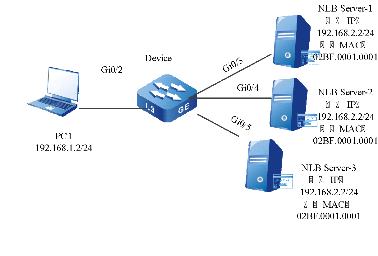
Figura 2-1 Rede de configuração do NLB
Etapas de configuração
- Passo 1:No dispositivo, configure a VLAN e o tipo de link de porta e o endereço IP .
# No dispositivo, crie VLAN2 e 3 .
Device#configure terminalDevice(config)#vlan 2,3
#Configure o tipo de link da porta gigabitethernet0/ 2 para acessar, permita que os serviços da VLAN2 passem, habilite a interação VLAN2 e configure o endereço IP para 192.168.1.1/24.
Device(config)#interface gigabitethernet 0/2Device(config-if-gigabitethernet0/2)#switchport mode accessDevice(config-if-gigabitethernet0/2)#switchport access vlan 2Device(config-if-gigabitethernet0/2)#exitDevice(config)#interface vlan 2Device(config-if-vlan2)#ip address 192.168.1.1 255.255.255.0Device(config-if-vlan2)#exit
o tipo de link de porta em gigabitethernet 0/3 – gigabitethernet 0/5 do Device to Access, permita a passagem dos serviços da VLAN2, habilite a interface VLAN2 e configure o endereço IP para 192.168.1.1/24 (omitido).
- Passo 2:Configurar o grupo de reflexão.
#Configure o grupo de reflexão 1 e selecione qualquer porta do dispositivo para adicionar ao grupo de reflexão.
Device(config)#serviceloop-group 1Device (config)# interface gigabitethernet 0/6Device(config-if-gigabitethernet0/6)#serviceloop-group 1 activeDevice(config-if-gigabitethernet0/6)#exit
- Passo 3:Configurar multiportas MAC.
#No dispositivo, configure a multiporta MAC e especifique a porta de saída como gi0/3-gi0/5 .
Device#configure terminalDevice(config)#mac-address multiport 02BF.1.1 vlan 3 interface gigabitethernet 0/3,0/4,0/5Device(config)#exit
- Passo 4:Configurar o ARP estático .
# No dispositivo, configure o ARP estático e vincule o grupo de reflexão.
Device#configure terminalDevice(config)# arp 192.168.2.2 02bf.1.1 vlan 3 serviceloop-group 1Device(config)#exit
- Passo 5:Confira o resultado .
#Visualize o grupo de reflexão.
Device# show serviceloop-groupserviceloop group 1Description:Number of ports in total: 1serviceloop port: gigabitethernet0/6
#Visualize a multiporta MAC.
Device# show mac-address multiportmac vlan interface02BF.0001.0001 3 gi0/3-0/5
#Visualizar ARP . _
Device# show arpProtocol Address Age (min) Hardware Addr Type Interface SwitchportInternet 192.168.1.1 - 0001.7a6a.011e ARPA vlan2 ---Internet 192.168.2.1 - 0001.7a6a.011e ARPA vlan3 ---Internet 192.168.2.2 - 02bf.0001.0001 ARPA vlan3 gigabitethernet0/3Internet 192.168.2.2 - 02bf.0001.0001 ARPA vlan3 gigabitethernet0/4Internet 192.168.2.2 - 02bf.0001.0001 ARPA vlan3 gigabitethernet0/5
# Ao acessar o IP do cluster do servidor NLB do PC, cada servidor pode receber o pacote.